P3960 Network Topology#
The following sections describe P3960 networking.
P3960 Network Topology#
P3960-TS2
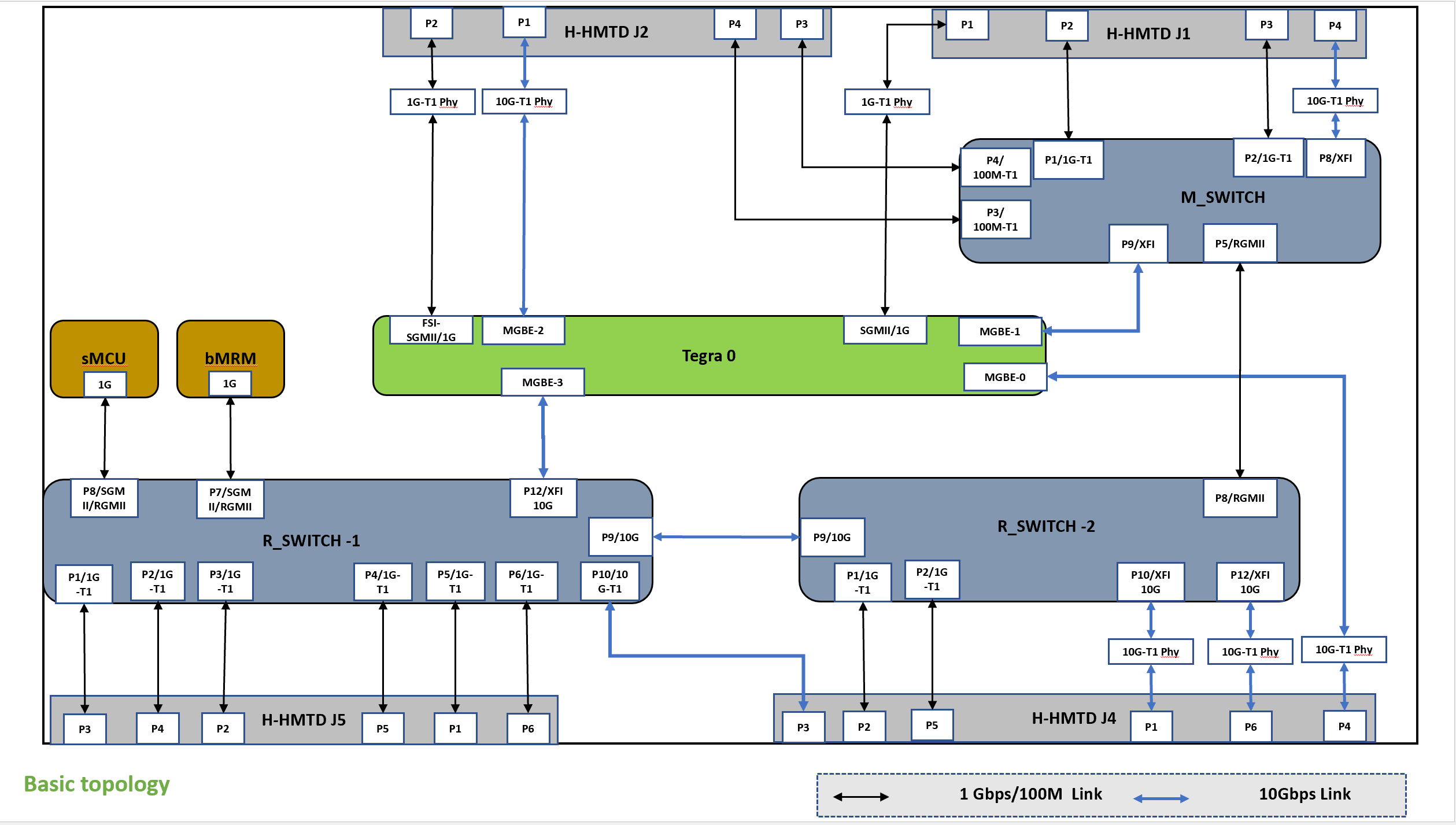
TS2: Ethernet ports to HMTD mapping
P3960-TS3
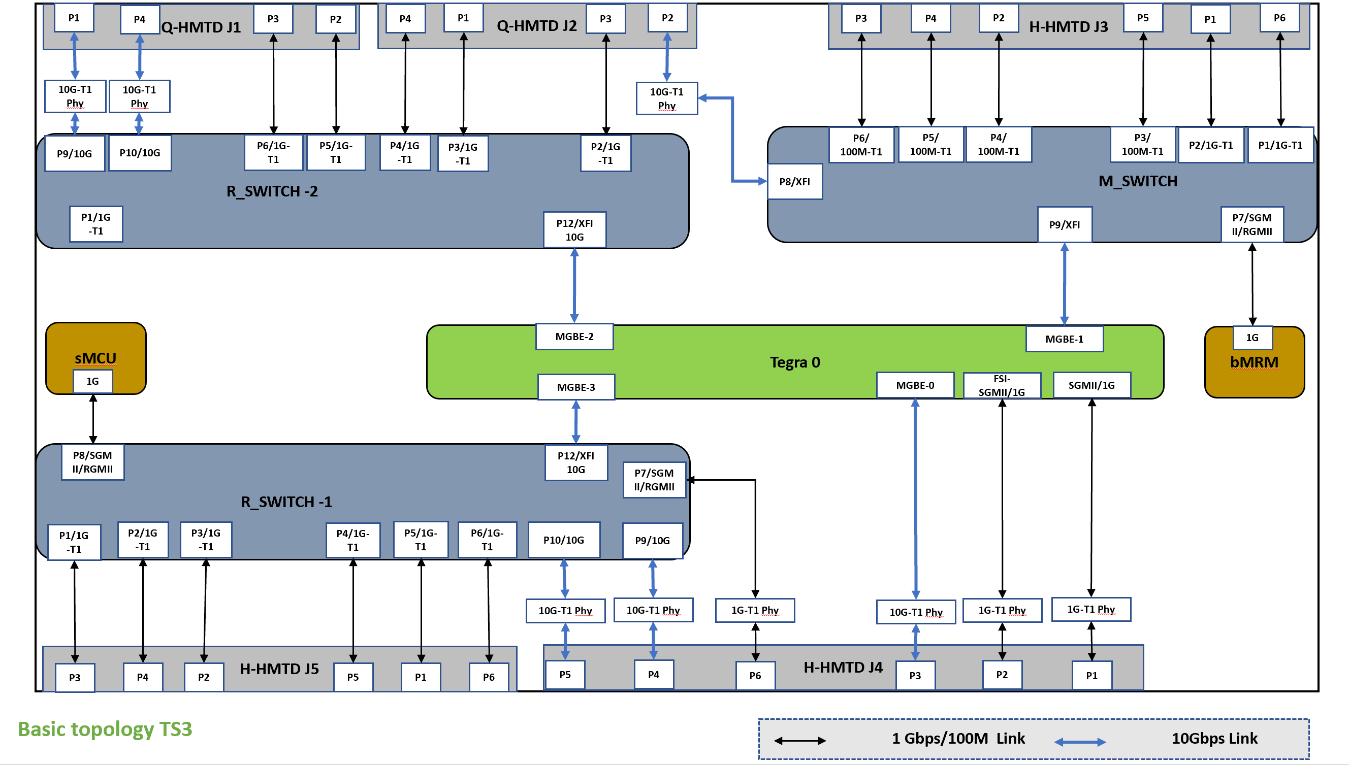
TS3: Ethernet ports to HMTD mapping
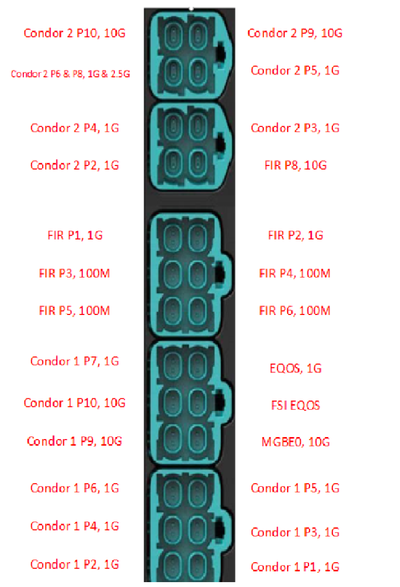
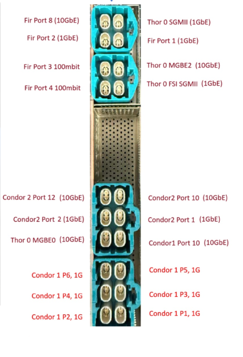
Board External Connectors#
(Common for all variant i.e TS2, TS3 etc..)
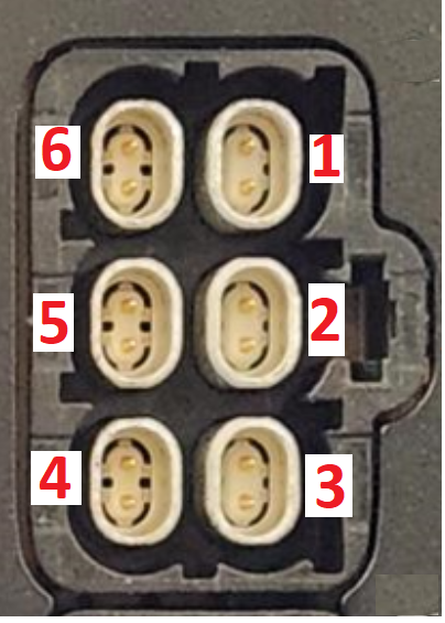
HEX HMTD
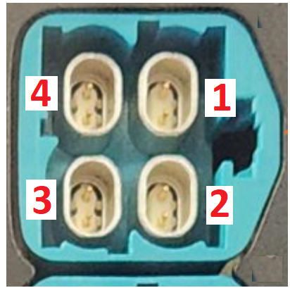
QUAD HMTD
The following is the channel map of HMTD:
P3960 External Connector Port - Mapping to Switch/Controller#
P3960-TS2#
Ethernet H-MTD x4 Connector-J1
Port |
Connected to |
|---|---|
1 |
Tegra_0 EQOS |
2 |
M_Switch (88Q5152) Port 1 |
3 |
M_Switch (88Q5152) Port 2 |
4 |
M_Switch (88Q5152) Port 8 |
Ethernet H-MTD x4 Connector-J2
Port |
Connected to |
|---|---|
1 |
Tegra_0 MGBE2 |
2 |
Tegra_0 FSI 1G |
3 |
M_Switch (88Q5152) Port 4 |
4 |
M_Switch (88Q5152) Port 3 |
Ethernet H-MTD x6 Connector-J4
Port |
Connected to |
|---|---|
1 |
R_Switch-2 (RTL907xD) Port 10 |
2 |
R_Switch-2 (RTL907xD) Port 1 |
3 |
R_Switch-1 (RTL907xD) Port 10 |
4 |
Tegra_0 MGBE0 |
5 |
R_Switch-2 (RTL907xD) Port 2 |
6 |
R_Switch-2 (RTL907xD) Port 12 |
Ethernet H-MTD x6 Connector-J5
Port |
Connected to |
|---|---|
1 |
R_Switch-1 (RTL907xD) Port 5 |
2 |
R_Switch-1 (RTL907xD) Port 3 |
3 |
R_Switch-1 (RTL907xD) Port 1 |
4 |
R_Switch-1 (RTL907xD) Port 2 |
5 |
R_Switch-1 (RTL907xD) Port 4 |
6 |
R_Switch-1 (RTL907xD) Port 6 |
P3960-TS3#
Ethernet H-MTD x4 Connector-J1
Port |
Connected to |
|---|---|
1 |
R_Switch-2 (RTL907xD) Port 9 |
2 |
R_Switch-2 (RTL907xD) Port 5 |
3 |
R_Switch-2 (RTL907xD) Port 6 |
4 |
R_Switch-2 (RTL907xD) Port 10 |
Ethernet H-MTD x4 Connector-J2
Port |
Connected to |
|---|---|
1 |
R_Switch-2 (RTL907xD) Port 3 |
2 |
M_Switch (88Q5152) Port 8 |
3 |
R_Switch-2 (RTL907xD) Port 2 |
4 |
R_Switch-2 (RTL907xD) Port 4 |
Ethernet H-MTD x6 Connector-J3
Port |
Connected to |
|---|---|
1 |
M_Switch (88Q5152) Port 2 |
2 |
M_Switch (88Q5152) Port 4 |
3 |
M_Switch (88Q5152) Port 6 |
4 |
M_Switch (88Q5152) Port 5 |
5 |
M_Switch (88Q5152) Port 3 |
6 |
M_Switch (88Q5152) Port 1 |
Ethernet H-MTD x6 Connector-J4
Port |
Connected to |
|---|---|
1 |
Tegra_0 EQOS 1G |
2 |
Tegra_0 FSI 1G |
3 |
Tegra_0 MGBE0 |
4 |
R_Switch-1 (RTL907xD) Port 9 |
5 |
R_Switch-1 (RTL907xD) Port 10 |
6 |
R_Switch-1 (RTL907xD) Port 7 |
Ethernet H-MTD x6 Connector-J5
Port |
Connected to |
|---|---|
1 |
R_Switch-1 (RTL907xD) Port 5 |
2 |
R_Switch-1 (RTL907xD) Port 3 |
3 |
R_Switch-1 (RTL907xD) Port 1 |
4 |
R_Switch-1 (RTL907xD) Port 2 |
5 |
R_Switch-1 (RTL907xD) Port 4 |
6 |
R_Switch-1 (RTL907xD) Port 6 |
P3960 Network Configuration#
The following table describes the network port configurations of P3960 variants.
P3960-TS2#
The following table describes the network port configurations of P3960-TS2.
Node |
Controller/Switch Port |
Mode & Speed |
T1 Role |
PHY present |
L2 switch forwarding restriction |
|---|---|---|---|---|---|
Tegra |
EQOS |
1G-BASE-T1 |
Primary |
Yes |
No restriction |
Tegra |
MGBE0 |
10G-BASE-T1 |
Primary |
Yes |
No restriction |
Tegra |
MGBE1 |
10G-XFI |
NA |
No |
No restriction |
Tegra |
MGBE2 |
10G-BASE-T1 |
Primary |
Yes |
No restriction |
Tegra |
MGBE3 |
10G-XFI |
NA |
No |
No restriction |
Tegra |
FSI 1G |
1G-BASE-T1 |
Primary |
Yes |
No restriction |
R_Switch-1 (RTL907xD) |
P1 |
1G-BASE-T1 |
Primary |
Yes (Internal) |
No restriction |
R_Switch-1 (RTL907xD) |
P2 |
1G-BASE-T1 |
Primary |
Yes (Internal) |
No restriction |
R_Switch-1 (RTL907xD) |
P3 |
1G-BASE-T1 |
Primary |
Yes (Internal) |
No restriction |
R_Switch-1 (RTL907xD) |
P4 |
1G-BASE-T1 |
Primary |
Yes (Internal) |
No restriction |
R_Switch-1 (RTL907xD) |
P5 |
1G-BASE-T1 |
Primary |
Yes (Internal) |
No restriction |
R_Switch-1 (RTL907xD) |
P6 |
1G-BASE-T1 |
Primary |
Yes (Internal) |
No restriction |
R_Switch-1 (RTL907xD) |
P7 |
1G-RGMII/SGMII |
NA |
No |
No restriction |
R_Switch-1 (RTL907xD) |
P8 |
1G-RGMII/SGMII |
NA |
No |
No restriction |
R_Switch-1 (RTL907xD) |
P9 |
10G-USXGMII |
NA |
No |
No restriction |
R_Switch-1 (RTL907xD) |
P10 |
10G-BASE-T1 |
Primary |
Yes |
No restriction |
R_Switch-2 (RTL907xD) |
P1 |
1G-BASE-T1 |
Primary |
Yes (Internal) |
No restriction |
R_Switch-2 (RTL907xD) |
P2 |
1G-BASE-T1 |
Primary |
Yes (Internal) |
No restriction |
R_Switch-2 (RTL907xD) |
P8 |
1G-RGMII |
NA |
No |
No restriction |
R_Switch-2 (RTL907xD) |
P9 |
10G-USXGMII |
NA |
No |
No restriction |
R_Switch-2 (RTL907xD) |
P10 |
10G-BASE-T1 |
Primary |
Yes |
No restriction |
R_Switch-2 (RTL907xD) |
P12 |
10G-BASE-T1 |
Primary |
Yes |
No restriction |
M_Switch (88Q5152) |
P1 |
1G-BASE-T1 |
Primary |
Yes (Internal) |
No restriction |
M_Switch (88Q5152) |
P2 |
1G-BASE-T1 |
Primary |
Yes (Internal) |
No restriction |
M_Switch (88Q5152) |
P5 |
1G-RGMII |
Primary |
Yes |
No restriction |
M_Switch (88Q5152) |
P8 |
10G-BASE-T1 |
Primary |
Yes |
No restriction |
M_Switch (88Q5152) |
P9 |
10G-XFI |
NA |
No |
No restriction |
P3960-TS3#
The following table describes the network port configurations of P3960-TS3.
Node |
Controller/Switch Port |
Mode & Speed |
T1 Role |
PHY present |
L2 switch forwarding restriction |
|---|---|---|---|---|---|
Tegra |
EQOS |
1G-BASE-T1 |
Primary |
Yes |
No restriction |
Tegra |
MGBE0 |
10G-BASE-T1 |
Primary |
Yes |
No restriction |
Tegra |
MGBE1 |
10G-XFI |
NA |
No |
No restriction |
Tegra |
MGBE2 |
10G-XFI |
NA |
No |
No restriction |
Tegra |
MGBE3 |
10G-XFI |
NA |
No |
No restriction |
Tegra |
FSI 1G |
1G-BASE-T1 |
Primary |
Yes |
No restriction |
R_Switch-1 (RTL907xD) |
P1 |
1G-BASE-T1 |
Primary |
Yes (Internal) |
No restriction |
R_Switch-1 (RTL907xD) |
P2 |
1G-BASE-T1 |
Primary |
Yes (Internal) |
No restriction |
R_Switch-1 (RTL907xD) |
P3 |
1G-BASE-T1 |
Primary |
Yes (Internal) |
No restriction |
R_Switch-1 (RTL907xD) |
P4 |
1G-BASE-T1 |
Primary |
Yes (Internal) |
No restriction |
R_Switch-1 (RTL907xD) |
P5 |
1G-BASE-T1 |
Primary |
Yes (Internal) |
No restriction |
R_Switch-1 (RTL907xD) |
P6 |
1G-BASE-T1 |
Primary |
Yes (Internal) |
No restriction |
R_Switch-1 (RTL907xD) |
P7 |
1G-RGMII/SGMII |
Primary |
Yes |
No restriction |
R_Switch-1 (RTL907xD) |
P8 |
1G-RGMII/SGMII |
NA |
No |
No restriction |
R_Switch-1 (RTL907xD) |
P9 |
10G-BASE-T1 |
Primary |
Yes |
No restriction |
R_Switch-1 (RTL907xD) |
P10 |
10G-BASE-T1 |
Primary |
Yes |
No restriction |
R_Switch-1 (RTL907xD) |
P12 |
10G-XFI |
NA |
No |
No restriction |
R_Switch-2 (RTL907xD) |
P2 |
1G-BASE-T1 |
Primary |
Yes (Internal) |
No restriction |
R_Switch-2 (RTL907xD) |
P3 |
1G-BASE-T1 |
Primary |
Yes (Internal) |
No restriction |
R_Switch-2 (RTL907xD) |
P4 |
1G-BASE-T1 |
Primary |
Yes (Internal) |
No restriction |
R_Switch-2 (RTL907xD) |
P5 |
1G-BASE-T1 |
Primary |
Yes (Internal) |
No restriction |
R_Switch-2 (RTL907xD) |
P6 |
1G-BASE-T1 |
Primary |
Yes (Internal) |
No restriction |
R_Switch-2 (RTL907xD) |
P9 |
10G-BASE-T1 |
Primary |
Yes |
No restriction |
R_Switch-2 (RTL907xD) |
P10 |
10G-BASE-T1 |
Primary |
Yes |
No restriction |
R_Switch-2 (RTL907xD) |
P12 |
10G-XFI |
NA |
No |
No restriction |
M_Switch (88Q5152) |
P1 |
1G-BASE-T1 |
Primary |
Yes (Internal) |
No restriction |
M_Switch (88Q5152) |
P2 |
1G-BASE-T1 |
Primary |
Yes (Internal) |
No restriction |
M_Switch (88Q5152) |
P3 |
100M-BASE-T1 |
Primary |
Yes (Internal) |
No restriction |
M_Switch (88Q5152) |
P4 |
100M-BASE-T1 |
Primary |
Yes (Internal) |
No restriction |
M_Switch (88Q5152) |
P5 |
100M-BASE-T1 |
Primary |
Yes (Internal) |
No restriction |
M_Switch (88Q5152) |
P6 |
100M-BASE-T1 |
Primary |
Yes (Internal) |
No restriction |
M_Switch (88Q5152) |
P7 |
1G-RGMII/SGMII |
NA |
No |
No restriction |
M_Switch (88Q5152) |
P8 |
10G-BASE-T1 |
Primary |
Yes |
No restriction |
M_Switch (88Q5152) |
P9 |
10G-XFI |
NA |
No |
No restriction |
Note
10G Dongle (P3584) has Base T1 Port role set to Primary mode by default and it does not support Auto-negotiation. Hence user connecting 10G dongle to 3960 Base-T1 port will have to change the 10G Base-t1 role of dongle to Secondary role using the “sm 0” command in dongle UART console.
For all 1G and 100M speed ports, 1G dongle i.e P3751 must be used. For all 10G speed ports, 10G dongle i.e P3584 must be used. 1G dongle(P3751) does not support 10G speed and 10G dongle (P3584) does not support 1G/100M speed.
Steps:
Connect the dongle type C port to host machine using USB cable.
Open the dongle uart console using command
sudo minicom -D /dev/ttyACM0(ttyACM device number can vary based on the devices connected)Run command
sm 0.Reset/restart the 3960 board, if needed.