A²B Interfaces#
DevKit |
Transceiver software name |
Transceiver Part Name |
Supported Node Capability |
Node I²C Address |
A²B Bus Address |
Port Name |
Harness Connector - Port No. |
Pin No. |
Pin No. on Harness Connector |
Drive Thor™ |
A²B1 |
AD2433 |
Main |
0x68 |
0x69 |
Port A |
VH1 - P7 |
A²B_P - 4 |
38 |
A²B_N - 5 |
39 |
||||||||
Sub |
Port B |
VH1 - P8 |
A²B_P - 2 |
42 |
|||||
A²B_N - 3 |
43 |
||||||||
A²B2 |
AD2433 |
Main |
0x6a |
0x6b |
Port B |
VH1 - P8 |
A²B_P - 4 |
44 |
|
A²B_N - 5 |
45 |
||||||||
A²B3 |
AD2433 |
Main |
0x6c |
0x6d |
Port B |
VH1 - P8 |
A²B_P - 6 |
46 |
|
A²B_N - 7 |
47 |
A²B Audio#
For playback and recording over I²S connected to A²B, see the sections below for further details.
DriveOS Thor™ is equipped with three A²B AD2433 transceivers, as illustrated below. Note that Port A operates as a sub node, while Port B operates as a main node.
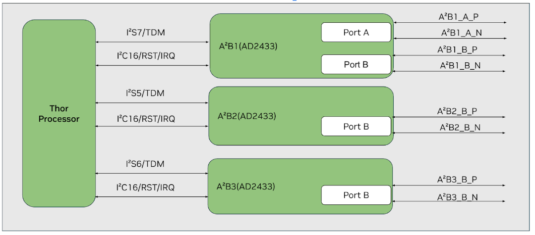
Note
A²B transceiver setup depends on the availability of FSYNC clock on connected I2S. Therefore, clocks are enabled by default for all I2S connected to A²B on DriveOS Thor™. In case, one plans to use A²B on DriveOS Thor™ as sub node, remove “clock-on” property from relevant I2S node in audio server DT. For more information on audio server DT, refer “Audio Virtualization Architecture” section.
AD2433 Speaker Playback#
When trying to play back audio for different channel counts, make sure to add the relevant I2S node configuration in relevant audio server device tree as per below guideline in “A²Bx Bus Configuration Script” section. The following examples demonstrate A2B1 Port B speaker playback configurations with different channel counts:
8-Channel Speaker Playback#
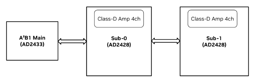
In this example, A2B1 Port B from the board connects to two sub nodes, each featuring a 4-channel Class D amplifier integrated with an AD2428 A²B transceiver, arranged in a daisy-chain configuration.
Routing Commands
// Route ADMAIF1 Output to I2S7
amixer –c 0 cset name="I2S7 Mux" "ADMAIF1"A²B transceiver setup
// Configure main and subnodes on the audio communication link or A²B bus
sudo ./a2b_configure_common.sh -b 32 -a 0x68 -n 2 -c 8 -s 32 -r 48000 -p 4 -m 1Testing commands
aplay -D hw:0,0 -f S32_LE -c 8 -r 48000 sample1.wav
16-Channel Speaker Playback#
In this example, A2B1 Port B connects to four sub nodes with AD2428 A²B transceivers in daisy-chain configuration, each featuring a 4-channel Class D amplifier.
Routing Commands
amixer –c 0 cset name="I2S7 Mux" "ADMAIF1"A²B transceiver setup
// Configure main and subnodes on the audio communication link or A²B bus
sudo ./a2b_configure_common.sh -b 32 -a 0x68 -n 4 -c 16 -s 32 -r 48000 -p 4 -m 1Testing commands
aplay -D hw:0,0 -f S32_LE -c 16 -r 48000 sample1.wav
32-Channel Speaker Playback#
In this example, A2B1 Port B connects to eight sub nodes with AD2428 A²B transceivers in daisy-chain configuration, each featuring a 4-channel Class D amplifier. Note that A²B protocol does not support 32ch with 32bps due to protocol limitations, so 16-bit samples are used.
Routing Commands
amixer –c 0 cset name="I2S7 Mux" "ADMAIF1"A²B transceiver setup
// Configure main and subnodes on the audio communication link or A²B bus
sudo ./a2b_configure_common.sh -b 16 -a 0x68 -n 8 -c 32 -s 16 -r 48000 -p 4 -m 1Testing commands
aplay -D hw:0,0 -f S16_LE -c 32 -r 48000 sample1.wav
AD2433 Microphone Capture#
When trying to capture audio for different channel counts, make sure to add the relevant I2S node configuration in relevant audio server device tree as per below guideline in “A²Bx Bus Configuration Script” section. The following examples demonstrate A2B1 Port B microphone capture configurations with different channel counts:
8-Channel Microphone Capture#
In this example, A2B1 Port B from the board is connected to two sub nodes, each with a 4-channel Mic array integrated with an AD2425 A²B transceiver.
Routing commands
// Route I2S7 Output to ADMAIF1
amixer –c 0 cset name="ADMAIF1 Mux" "I2S7"A²B transceiver setup
// Configure main and subnode on the audio communication link
sudo ./a2b_configure_common.sh -b 32 -a 0x68 -n 2 -c 8 -s 32 -r 48000 -p 4 -m 0Testing commands
arecord -D hw:0,0 -r 48000 -c 8 -f S32_LE sample_rec.wav
16-Channel Microphone Capture#
In this example, A2B1 Port B is connected to four sub nodes with AD2428 A²B transceivers in daisy-chain configuration, each with a 4-channel Mic array.
Routing commands
// Route I2S7 Output to ADMAIF1
amixer –c 0 cset name="ADMAIF1 Mux" "I2S7"A²B transceiver setup
// Configure main and subnode on the audio communication link
sudo ./a2b_configure_common.sh -b 32 -a 0x68 -n 4 -c 16 -s 32 -r 48000 -p 4 -m 0Testing commands
arecord -D hw:0,0 -r 48000 -c 16 -f S32_LE sample_rec.wav
32-Channel Microphone Capture#
In this example, A2B1 Port B is connected to eight sub nodes with AD2428 A²B transceivers in daisy-chain configuration, each with a 4-channel Mic array. Note that A²B protocol does not support 32ch with 32bps due to protocol limitations, so 16-bit samples are used.
Routing commands
// Route I2S7 Output to ADMAIF1
amixer –c 0 cset name="ADMAIF1 Mux" "I2S7"A²B transceiver setup
// Configure main and subnode on the audio communication link
sudo ./a2b_configure_common.sh -b 16 -a 0x68 -n 8 -c 32 -s 16 -r 48000 -p 4 -m 0Testing commands
arecord -D hw:0,0 -r 48000 -c 32 -f S16_LE sample_rec.wav
A²B Main Node Internal Loopback#
In this example, A²B2 is set up for bus loopback using register settings. Unlike previous examples, there are no explicit connections from A²B2 ports as the loopback is configured internally.
Routing Commands
// Route I2S5 output to ADMAIF1 and ADMAIF1 output to I2S5
amixer –c 0 cset name="ADMAIF1 Mux" "I2S5"amixer –c 0 cset name="I2S5 Mux" "ADMAIF1"A²B transceiver setup
// Configure main and subnodes on the audio communication link or A²B bus
sudo /opt/nvidia/drive-linux/tools/audio/a2b_config_main.sh -i 16 -d 0x6a -f 2Testing commands
The testing commands are as follows:
aplay -D hw:0,0 -f S32_LE -c 8 -r 48000 sample1.wav &arecord -D hw:0,0 -r 48000 -c 8 -f S32_LE sample_rec.wav
A²Bx to A²By External Loopback#
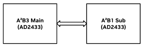
In this example, DevKit’s A²B3 Port B is connected to A²B1 Port A, enabling external loopback of the content played from A²B3 to A²B1. It’s important to note that A²B1 can function as a standalone subnode due to the presence of Port A.
Device Tree configuration
//Configure I2S7 as frame-slave per below patchset in relevant audio server device tree:
@@ -661,7 +661,7 @@
        nvidia,dai-link-7 {
            cpu-dai-name = "I2S7";
            format = "dsp_b";
-           frame-slave;
+           frame-master;
            bitclock-noninversion;
            frame-inversion;
            tx-mask = <0xFF>;
Routing commands
// Route I2S7 output to ADMAIF1 and ADMAIF1 output to I2S6
amixer –c 0 cset name="ADMAIF1 Mux" "I2S7"amixer –c 0 cset name="I2S6 Mux" "ADMAIF1"A²B transceiver setup
// Configure main and subnodes on the audio communication link or A²B bus
sudo /opt/nvidia/drive-linux/tools/audio/a2b_config_main.sh -i 16 -d 0x6c -f 5Testing commands
aplay -D hw:0,0 -f S32_LE -c 8 -r 48000 sample1.wav &arecord -D hw:0,0 -r 48000 -c 8 -f S32_LE sample_rec.wav
A²B Reduced Rate Usecase#
This section demonstrates the A²B Reduced Rate usecase
Configuration Details:#
- Master Node (TDM2):
Sample Rate: 48kHz
Bit Width: 32-bit
I2C Address: 0x6a (A2B2 main address)
- Slave Node (TDM2):
Sample Rate: 24kHz (0.5 × Main FSYNC)
Bit Width: 32-bit
I2C Address: 0x6b (A2B2 Bus address)
Configure I2S and ADMAIF routing:
amixer -c 0 cset name="I2S5 Mux" ADMAIF1amixer -c 0 cset name="ADMAIF1 Mux" I2S7Configure A²B nodes:
sudo ./a2b_configure_common.sh -b 16 -a 0x6a -t rrStart playback on main node (48kHz):
speaker-test -D hw:0,0 -t sine -F S32_LE -c 2 -r 48000Start recording on sub node (24kHz):
arecord -D hw:0,0 -r 24000 -c 2 -f S32_LE lpbk_recording.wavThe master node should successfully play audio at 48kHz
The slave node should successfully record audio at 24kHz
The recorded audio should maintain signal integrity despite the removal of alternate samples
The reduced rate feature is useful in scenarios where bandwidth optimization is required
A²Bx Bus Configuration Script#
This script is used to configure the A2B bus. It sets up the necessary parameters for the bus and performs the required configuration. Rest of the setup items listed below can be referred from above examples
Route i.e ADMAIF to I2S and vice versa
Trigger of playback/record
In addition, I2S channel count, channel mask and bit format needs to added in relevant I2S node per below sample guideline if needed
@@ -760,12 +760,12 @@
                        format = "dsp_b";
                        frame-slave;
                        bitclock-noninversion;
-                       tx-mask = <0xFF>;
-                       rx-mask = <0xFF>;
-                       bit-format = "s32_le";
+                       tx-mask = <0xFFFFFFFF>;
+                       rx-mask = <0xFFFFFFFF>;
+                       bit-format = "s16_le";
                        bclk_ratio = <1>;
                        srate = <48000>;
-                       num-channel = <8>;
+                       num-channel = <32>;
                };
                nvidia,dai-link-6 {
                        cpu-dai-name = "I2S6";
Usage
sudo ./a2b_configure_common.sh [options]
Options:
-b <Sample Size>:Sample size. Either 16 or 32.-a <A2B device address>:Main node device address on the I2C bus.-n <Sub node count>:Number of sub nodes.-c <Channel count>:Number of channels.-s <Sample rate>:Sample rate.-r <Sub node sample rate>: Sample rate for sub nodes.-p <TDM Channels>:Number of TDM channels.-m <Usecase>:Usecase. Either 0 for capture or 1 for playback.Constraints and Limitations:
The script supports the following combinations:
Capture with Infineon mic array boards (AD2428 based) for 8 channel 32 bit 2 boards, 16 channel 32 bit 4 boards, and 32 channel 16 bit 8 boards.
Playback with Class D Amp Spk Boards (AD2428 based) for 8 channel 32 bit 2 boards, 16 channel 32 bit 4 boards, and 32 channel 16 bit 8 boards.
The script assumes DriveOS Thor™ A²Bx as main node
Please note that the above script is just for reference and does not intend to cover all possible scenarios even in future, and you may need to customize it to fit your specific requirements.
Usage Examples
sudo ./a2b_configure_common.sh
             -b 16 -a 0x6a -n 8 -c 32 -s 16 -r 48000 -p 4 -m 0
sudo ./a2b_configure_common.sh
             -b 16 -a 0x68 -n 8 -c 32 -s 16 -r 48000 -p 4 -m 1
Setup of Custom A²B Bus#
In an automotive system, an A²B communication bus typically features a single main node and multiple subnodes. Each node, whether main or subordinate, requires an A²B transceiver, which must be configured per the prescribed programming sequence via I²C to enable the bus’s functionality.
Analog Devices (AD) is the primary provider of A²B (Automotive Audio Bus) transceivers. Analog Devices provides free SigmaStudio (http://www.analog.com/SigmaStudio) tools featuring an intuitive graphical user interface to architect, configure, and set up the A²B communication bus.
Note
SigmaStudio version > 4.6 may have some stability issues. Please get in touch with Analog Devices for the Sigma Studio setup for AD2433.
For example below, Sigma Studio 4.6 and A²B Software version 19.10.0 have been used.
While NVIDIA provides I²C programming scripts for specific A²B bus designs in the examples section, users creating custom A²B buses will need to follow these steps to obtain the necessary I²C programming:
Design the Audio Communication Link: Define the main node, subnodes, and their connections in the audio communication link. For guidance on building this schematic, refer to the AE_09_A2B_SigmaStudio_UserGuide.pdf located in the installation folder of the A²B Software.
A²B Bus Setup Sequence: The setup of the A²B bus involves programming the registers to bringup the main node, followed by the discovery and configuration of all nodes. Refer to the AD2433 datasheet for the discovery flow to understand the required setup sequence. Note that Bus Self-Discovery is not supported on this platform. For details on alternative discovery flows, consult the flow charts in the datasheet, which outline the correct register configuration and sequencing.
Configure A²B Transceivers: Once the schematic is completed, configure each component in the schematic as needed. For further instructions, refer to AE_09_A2B_SigmaStudio_UserGuide.pdf in the A²B Software’s installation folder.
Create I²C programming script: A valid A²B schematic can be exported into either C programming language or XML formats, with XML being the more readable option. To export the necessary A²B configuration, select the ‘Export System Configuration Files’ option in SigmaStudio, as outlined in the “‘Exporting A²B System Configuration Files’” section of the A²B SigmaStudio User Guide. Additionally, you can choose to export a ‘Command list’ in XML format, which contains the I²C programming sequence required for configuring the A²B nodes. Refer ‘Working with Configuration XML files’ for detailed information.
Use this command list to create the I²C programming script. Sample script can be referred from “AD2433 Speaker Playback” and “AD2433 Microphone Capture” sections.
Other I²C Programming Caveats#
The main node’s I²C address accesses the main transceiver’s registers, programmed via:
i2cset -y <I²C Bus> <A²B Main Address> <Reg Addr> <Reg Value>

Example for A²B1 main node:` i2cset -y 16 0x68 0x75 0x40`
The bus I²C address accesses the sub transceiver’s registers, programmed via:
i2cset -y <I²C Bus> <A²B Bus Address> <Reg Addr> <Reg Value>

Example for A²B1 sub node: `i2cset -y 16 0x69 0x3F 0x01`
Since sub nodes share a single bus address, set the sub node’s ID in A2B_NODEADR before writing. A2B_NODEADR is part of the main transceiver’s registers. Use A2B_NODEADR.NODE to select the subnode. Refer to the AD2433 datasheet for further details.
To program peripherals connected to sub transceivers, enable the A2B_NODEADR.PERI field along with programming in step 3. Be aware that the register spaces for sub transceivers and peripherals may differ. Some subnodes combine the transceiver and peripheral on a single chip with shared register space, while users may choose to chain a particular transceiver with a particular peripheral and may want to program each of them individually.
Disclaimer : The “Setup of Custom A²B Bus” section is intended to provide a basic introduction for a quick start and is not comprehensive. For detailed information and support, refer to resources provided by Analog Devices. You may have to create an account at https://www.analog.com/en/gated/a2b/a2b-technology.html for accessing resources and support from Analog Devices.