Table of Contents
Node
For the framework each processing step's functionality is a black box called node. It is an atomic algorithmic unit of execution.
In order to compose pipelines out of these building blocks they must provide their interface in a uniform way. That interface describes the input data as well as the output data which allows connecting multiple nodes to form a pipeline.
Port
An endpoint for input / output data is called a port. Each port has a name to uniquely identify them within a node and is strictly typed to check to which other endpoints it can be connected.
Pass
For the efficient utilization of compute resources the execution of a node is broken into individual passes. Each pass is running on a single compute resource, e.g. a CPU core, GPU, DLA. A pass is an atomic unit of execution from a scheduling point of view. Commonly the logic of a pass is not implemented in the node itself but in a DriveWorks modules instead.
By default all passes of a node are executed sequentially. For custom dependencies between passes within a node see non-sequential passes.

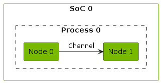
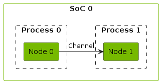
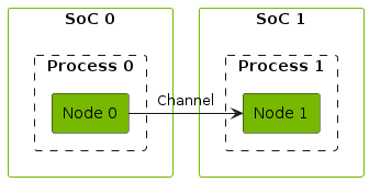
Channel
A connection between two endpoints is called a channel. The channel represents the data flow from the source (commonly an output port of one node) to the destination (commonly an input port of another node). A channel can be configured to use different transport protocols depending on the use case and application layout. Zero-copy transport is supported where possible:
- In-process shared memory
- Cross process shared memory
- Cross Engine (NvSciBuffer)
- Ethernet-based (Sockets)
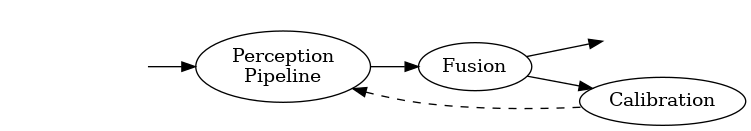
Directed Acyclic Graph (DAG)
The dataflow forms a directed graph where the CGF nodes are the vertices and the CGF channels are the edges. Each edge represents a data dependency.
The execution of nodes needs to happen in topological order to ensure data dependencies are fulfilled. For a topological ordering to exist the graph must be acyclic.
Since in real world application circular data flows are not uncommon, some edges need to be annotated as not being considered a data dependency to break the cycles. The resulting DAG describes the computational pipeline.
Graphlet Hierarchy
The complexity of a DAG naturally scales with the complexity of the application. As such the number of vertices and edges increases. To decompose such a complex graph it can be described as a hierarchy of subgraphs.
Each subgraph is called a graphlet and commonly encapsulates a functional unit. This not only keeps the complexity of each graphlet manageable but also enables reusing such graphlet - either within the same application or in other applications.

Component
From the outside a graphlet is a black box - similar to a node. A graphlet has the same interface: input / output ports and the processing steps are defined by the computational pipeline / the subgraph (rather than node passes). As such a graphlet can not only contain nodes but also other graphlets as vertices of the subgraph. The term component refers to either a node or a graphlet.