Camera Setup and Configuration
The platform provides multiple video and camera ports.
Before using these cameras with the NvMedia sample applications, the cameras must be attached to the ports in a specific order. If you fail to do so, NvMedia reports errors.
Before connecting/disconnecting cameras to/from the platform, disconnect the power. Failure to do so may damage the camera.
For information on setting up the board, see DRIVE AGX Orin Developer Kit_Hardware_Quick Start Guide.
Camera Interfaces
Maxim Integrated GMSL SERDES
The NVIDIA DRIVE® AGX Orin platform (P3710) provides GMSL camera interfaces. The GMSL camera interfaces:
- Provide 16 simultaneous GMSL camera inputs.Note:
The actual number of camera outputs supported depends on the resolution of the camera output, frame rate of the output, and power mode (specifically the Video Input (VI) and ISP HW clocks).
- Route camera data to either SoC.
- SoC generates a TSC_EDGE_OUT signal on a GPIO pin that is connected to all deserializers. This common PWM signal is then forwarded to all 16 GMSL cameras to achieve frame synchronization.
For information on the connectors, see the rear view board image in Setting Up Your Platform.
TI FPD-Link SERDES Support
Initial support for TI FPD-Link IV SERDES links is available in Drive OS 6.0.6.0, with the driver and source for the DS90UB9724 deserializer provided in conjunction with the DS90UB971 serializer. This is available in SIPL, with the P3714-B00 FPDLINK CIM. Driver and configuration support for the IMX728 FPD-Link camera module using the DS90UB971 serializer is also available.
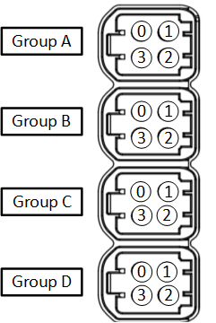
Mapping Connectors
Each GMSL camera group can be routed to the chip using a GMSL deserializer.
- GMSL cameras are organized into quads. For example, A, B, C and D as available.
- Different cameras may be used in different quads.
- When connecting or disconnecting the GMSL cameras, ensure the power is off. If the power is ON, the GMSL camera or the platform may be damaged.
- For Camera group A and B, I2C bus speed is 1Mhz. For Camera group C and D, I2C bus speed is 400KHz. Connect the GMSL cameras to the group with the correct I2C bus speed.
The camera mapping for the DRIVE AGX Orin Developer Kit (P3710-10) board is as follows:
Connecting the Cameras
The GMSL camera must be 8V tolerant. Refer to the platform datasheet for details on the electrical requirements for the GMSL camera.
Always turn off main power before connecting or disconnecting cameras.
To connect multiple cameras using the quad camera breakout cable
- Connect the quad camera breakout cable to the platform camera group A.
- Using the Fakra coax cable, connect the GMSL camera to the other end of the quad camera breakout cable.
- Connect any subsequent cameras to each connector of the quad camera breakout cable.
- The mapping of the quad camera breakout cable:
- Green: A0
- Red: A1
- Blue: A2
- White: A3
To run the sample applications
- Start camera capture using commands.
For example, for Valeo IMX728 B1 camera module connected to A0 port in the Group A, and an HDMI monitor is connected to the DP (DisplayPort) port. The commands are below.
Before using the
-doption with thenvsipl_cameraapplication, you must complete the following requirements:- Terminate Ubuntu Desktop
- Terminate
Desktop:
systemctl disable gdm systemctl stop gdm - Alternatively:
sudo service lightdm stop
sudo service gdm stop
- Terminate
Desktop:
- Terminate
X11
sudo pkill Xorg - Terminate any active Vulkan or OpenGL or Graphics applications.
sudo lsmod | grep nvidia-drm- If the output shows nvidia-drm, uninstall
drm:
sudo rmmod nvidia-drm
- Terminate Ubuntu Desktop
- Launch a terminal window and navigate to the following directory.
- On Ubuntu rootfs:
/opt/nvidia/drive-linux/samples/nvmedia/nvsipl/test/camera- On Yocto rootfs:
/opt/root/samples/nvmedia/nvsipl/test/camera - Enter this command.
sudo ./nvsipl_camera --platform-config "V728S1-120V1-FWC_CPHY_x4" --link-enable-masks "0x0001 0x0000 0x0000 0x0000" -d 0Where:
V728S1-120V1-FWC_CPHY_x4specifies the name of the platform configuration that describes the connection of image sensors to Orin based platforms.-d 1specifies the display number.-w 1specifies display window ID.
- To obtain the available display devices for Tegra, execute the following command:
./nvsipl_camera -hThe available display devices are identified.
- Select the desired display ID.