Shaded display re-visited: implementing a ray tracer in MDL
Ray tracing has come a long way since Whitted's legendary paper "An Improved Illumination Model for Shaded Display" and it's about time we pay tribute: Nowadays ray tracing on GPUs is so fast that it's actually feasible to implement a ray tracer inside a ray tracer.
For that we will use the Material Definition Language (MDL), which is fully supported inside NVIDIA Iray, a fast physically-based renderer. MDL is an easy-to-use domain specific language that describes a material by its two fundamental parts: A declarative material definition and a procedural programming language for function definitions. In this blog post we will concentrate on the second part and present some MDL functions that will be used for procedural content creation, ranging from a simple texture lookup to an actual fully fledged procedural image generator - using ray tracing.
Assume we already have a nice scene and now want to put an additional picture into an empty frame. And we not only want a picture, we want a picture of Whitted's iconic ray tracing scene!
 The scene we are rendering. We will procedurally create the framed image in MDL.
We'll start with a simplistic MDL function, loading just a bitmap texture from a file and attaching that to our objects material diffuse parameter input. We then access the actual filtered texels during rendering by the texture coordinate available through the MDL renderer state:
 Cheating: using a texture.
export color texlookup(uniform texture_2d texture = "diffuse.png")
{
    return tex::lookup_float3(coord: float2(state::texture_coordinate(0).x,state::texture_coordinate(0).y), tex: texture);
}

export material texlookup_example(uniform texture_2d diffuse_texture = "diffuse.png") = let
{
    bsdf diffuse_bsdf = df::diffuse_reflection_bsdf(tint: texlookup(texture: diffuse_texture));
} in material(surface: material_surface(scattering: diffuse_bsdf));
So far, so simple. But we don't just want to load a low resolution bitmap of that fixed image.
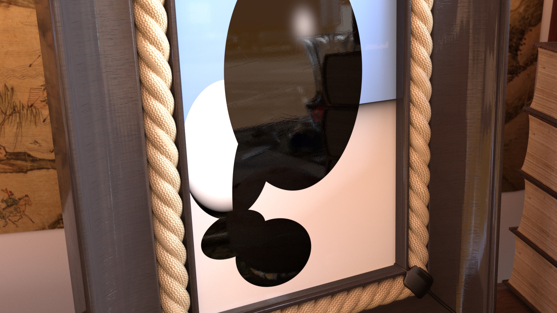
We actually want to procedurally create it during runtime. Because then we are able to zoom in arbitrarily close and we can interactively change parameters like sphere radius and checkerboard pattern. To do that, we'll do the same as Whitted did back then: Synthesizing the image from a virtual scene description using ray tracing. We'll start with a simple framework to shoot rays from a pinhole camera through an image plane and intersecting each ray with the spheres and the plane to find its closest intersection with an object:
 Simple camera code and ray-sphere intersection.
export color whitted_simple()
{
    float3 fwd((lookat-eye)/math::length(lookat-eye));
    float3 up(0.f,1.f,0.f);
    float3 right = math::cross(fwd,up);
    up = math::cross(right,fwd);

    //

    float3 uvw = state::texture_coordinate(0);

    float3 ray_pos(eye);
    float3 ray_dir = math::normalize((uvw.x-0.5f)*right + (uvw.y-0.5f)*up + (-0.5f/math::tan(math::PI*(1.f-fov/360.f)))*fwd);

    //

    intersection is = nearest_hit(ray_pos, ray_dir);

    if(is.hit_obj == nothing)
        return bg_color;
    else if(is.hit_obj == plane)
        return color(0.5f);
    else if(is.hit_obj == metal_sphere)
        return color(1.f);
    else
        return color(0.1f);
}
We first transform the incoming texture coordinate with our handmade camera vectors (constructed out of the two points eye, lookat and an up-vector), which provides us rays starting from the eye and passing through the image plane into our virtual scene. The nearest_hit() function intersects all scene objects (in our case the two spheres and a plane) and returns which object has been hit. For now we leave it at simply coloring each object slightly different.
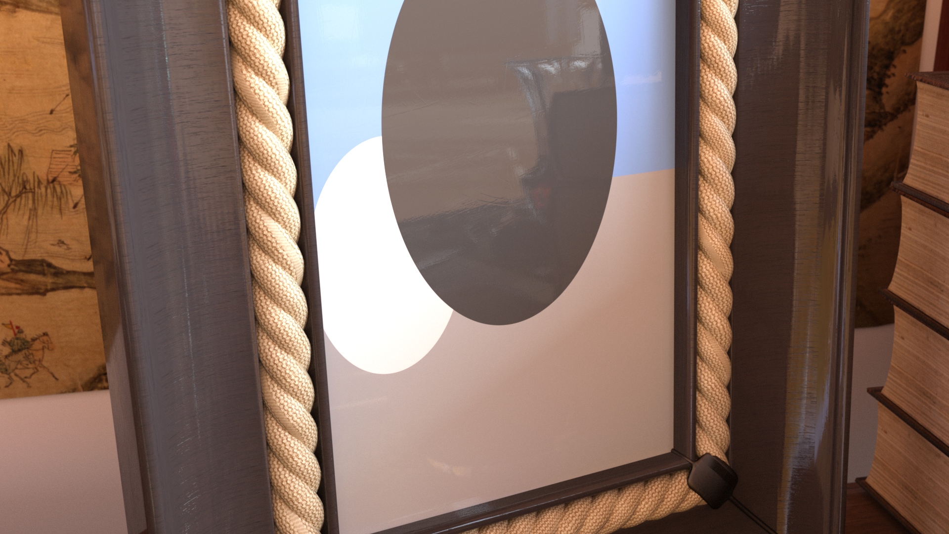
In the next step we'll extend this example by a simplistic lighting step including an additional shadow ray from the intersection point to the light source to determine occlusion:
 Ray-traced shadows and a Phong-style highlight.
export color whitted_lighting()
{
    [...] // ray setup, find nearest intersection and assign each object an color "oc", roughly same code as above

    float shadow_acne_offset = 0.001f;

    float3 shad_ray_pos = is.hit_point + is.normal*shadow_acne_offset;
    float3 shad_ray_dir = math::normalize(light_pos-shad_ray_pos);

    float cos_ln = math::max(math::dot(shad_ray_dir,is.normal),0.f);
    float3 shad_refl = reflect(shad_ray_dir, is.normal);
    float cos_rv = math::max(math::dot(shad_refl,ray_dir),0.f);

    intersection shad_is = nearest_hit(shad_ray_pos, shad_ray_dir);

    if(shad_is.hit_obj == nothing) // not in shadow?
    {
        if(is.hit_obj == metal_sphere)
            oc *= (math::pow(cos_rv,metal_sphere_exp) + cos_ln) * light_emission;
        else if(is.hit_obj == plane)
            oc *= cos_ln * light_emission;
        else // glass sphere
            oc *= math::pow(cos_rv,glass_sphere_exp) * light_emission;
    }
    else
        oc = 0.f;

    return oc;
}
Note that the lighting here is designed to match the look and feel of the original picture, and not to feature actual "physical correctness". This will not break the physical plausibility of the Iray rendering: MDL was specifically designed to hide the actual light transport simulation from the material design itself. Since we are merely programming the material inputs attached to the distribution functions (in this example a simple diffuse BRDF) of the material, or the parameters to stack multiple layers on top of each other, this will always yield a physically plausible material.
Now that we have some 80s style lighting, we can continue adding perfect reflections and refractions. This means instead of tracing just a single ray in the virtual scene, and lighting and shadowing when interacting with an object, we now have to continue shooting more ray(s) recursively, depending on the material of the sphere(s) and plane, until we do not find any intersection anymore (=hitting the "sky"). To reproduce the look of the original image closely, we will use two spheres to describe the hull of the glass sphere to get similar refraction effects. As rays now can be either refracted or reflected when interacting with the glass sphere, we manage a small stack to keep one of these two interactions on the ray stack, while we finish the other one directly. This is necessary as the MDL specification does not allow for recursion for performance reasons. Any serious graphics programmer implementing ray or path tracing recursively should rethink about this anyway. :-)
As a bonus touch we cut off the infinite plane and add a checkerboard pattern to it.
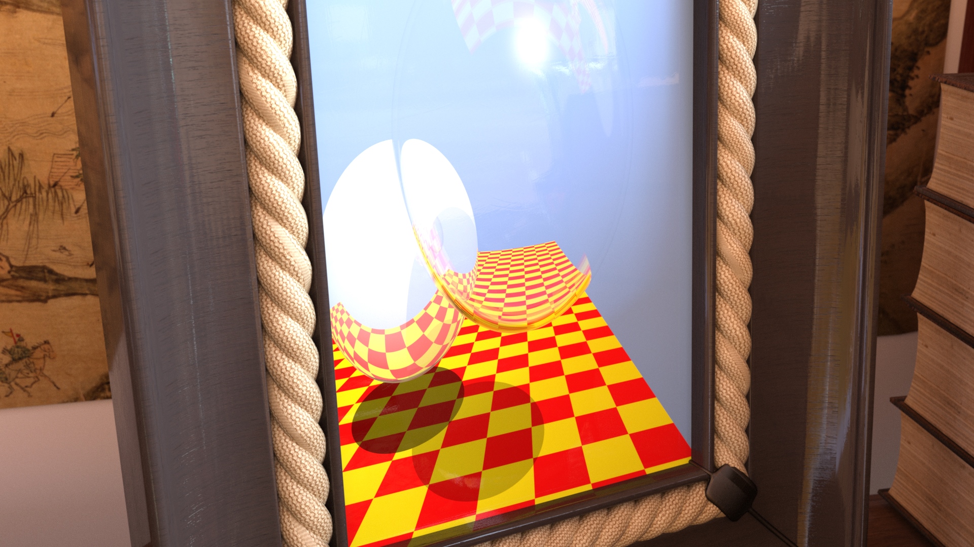 The full thing: reflections, refractions, Fresnel, and a checkboard.
export color whitted(float glass_sphere_radius_outer = 1.f, float checker_size = 1.5f)
{
    [...] // camera setup

    color acc(0.f,0.f,0.f);
    float weight = 1.f;
    bool  ior_inside = false;

    int   current_trace_depth = 0;

    int   current_stack = 0;
    stack_entry[stack_depth] stack;

    //

    while(true)
    {
        if(current_trace_depth >= trace_depth)
        {
            if(current_stack > 0)
            {
                current_stack--;
                ray_pos    = stack[current_stack].ray_pos;
                ray_dir    = stack[current_stack].ray_dir;
                weight     = stack[current_stack].weight;
                ior_inside = stack[current_stack].ior_inside;
                current_trace_depth = stack[current_stack].trace_depth;
            }
            else
                break;
        }

        [...] // find nearest intersection and assign each object an color "oc", roughly same code as above
        [...] // do the lighting and shadow tracing as before, accumulate in "acc", adapt "weight" by object material
        [...] // in addition compute reflection and refraction, depending on hit object

        [...] // if the glass sphere was hit and we need to do both reflection and refraction:
        {
            if(current_stack < stack_depth &&       // only do both reflection + refraction if still room on stack
               current_trace_depth+1 < trace_depth) // and trace depth max not reached
            {
                stack[current_stack].ray_pos = is.hit_point + is.normal*shadow_acne_offset;
                stack[current_stack].ray_dir = reflect(ray_dir, is.normal);
                stack[current_stack].weight = weight*f;
                stack[current_stack].ior_inside = ior_inside;
                stack[current_stack].trace_depth = current_trace_depth+1;
                current_stack++;
            }
        }

        current_trace_depth++;
    }

    return acc;
}
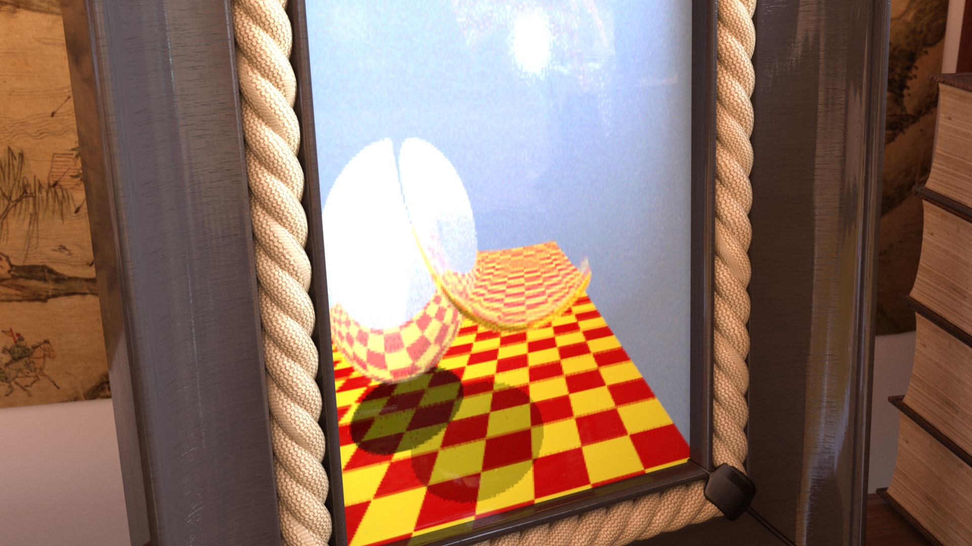
And here a full shot of our procedural:
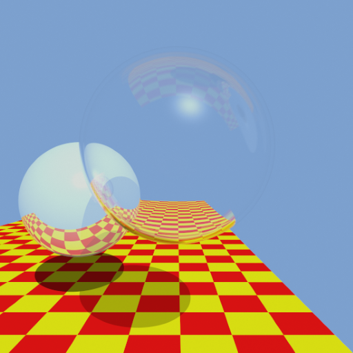 This is the procedural that our MDL code renders at runtime.
This blog was authored by Carsten Waechter and Matthias Raab
The complete MDL source for this project can be found Here
Both Iray and MDL are part of NVIDIA DesignWorks.