Table of Contents
Description
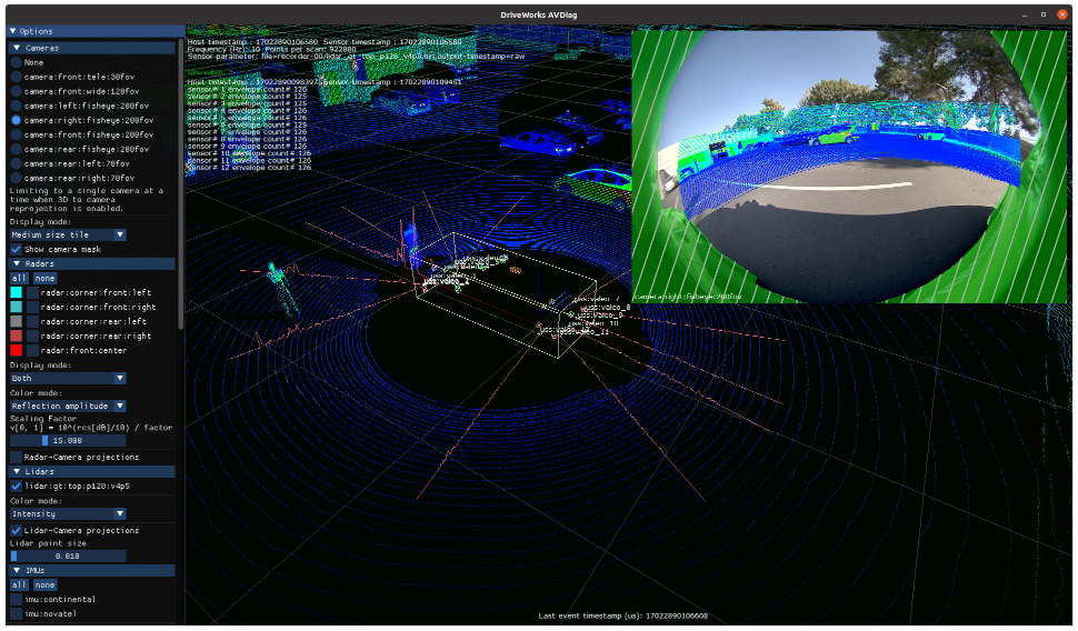
The AVDiag tool plays recorded and live sensor data for visualization given a rig configuration file. It also provides a GUI for manual sensor testing (e.g., making sure camera frustums are oriented correctly). Test results and runtime information are saved into an output session directory.
The aim is to provide a visualization tool for live and recorded data of all sensor types, and an unified and traceable testing solution that can be used for vehicle bring-up.
Prerequisites
This tool is available on the x86 Host System, NVIDIA DRIVE™ OS Linux and NVIDIA DRIVE™ OS QNX.
Running the Tool in Visualization Only Mode
Run the tool by executing:
./avdiag   --rig <path to rig file>
           [--rig-sensor-filter=<sensor name filter REGEX, e.g., 'camera|lidar']
For running individual sensors, the path to the data file can be directly specified:
./avdiag   --camera <path to video>
           --timestamp <path to video timestamp file>
           --can <path to CAN data>
           --data <path to Data sensor data>
           --imu <path to IMU data>
           --gps <path to GPS data>
           --lidar <path to Lidar data>
           --radar <path to Radar data>
           --ultrasonic <path to USS data>
Run $ ./avdiag --help for a full list of supported parameters.
Running the Tool with Test Cases GUI
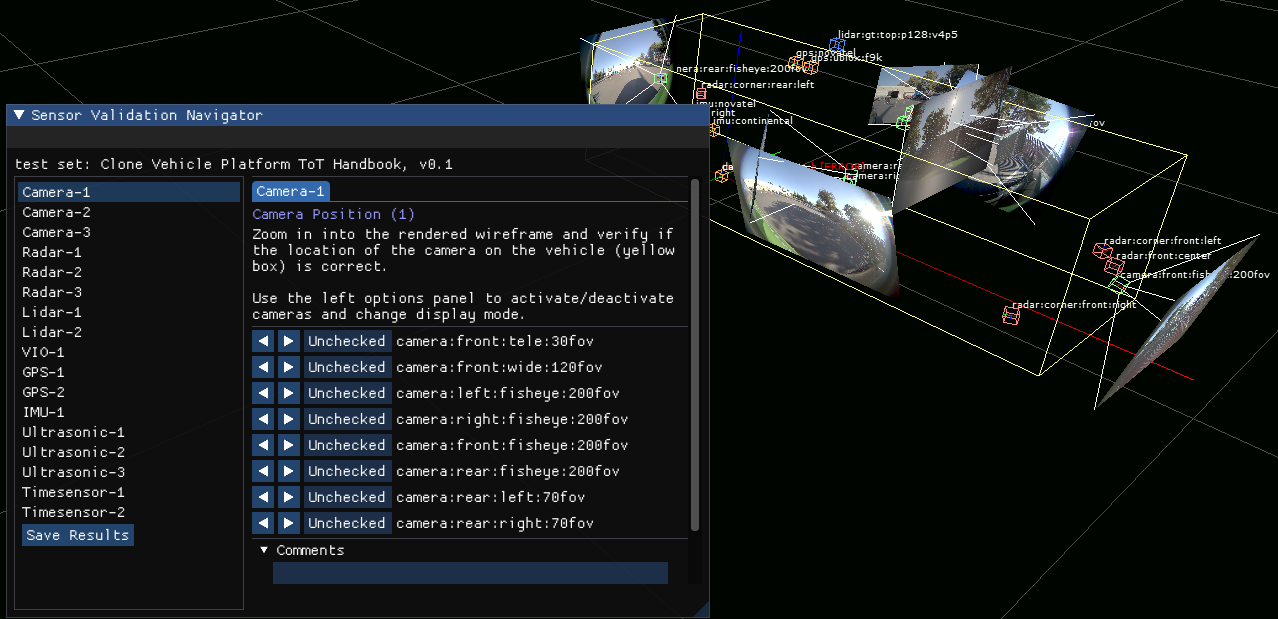
AVDiag is also a testing solution that can be used for vehicle bring-up. It has a test case GUI composed of instructions and a panel for entering test results. At the end of execution, all results will be saved to the output directory.
The optional command line parameter --config <test cases file path> will activate the testing GUI.
Defining a JSON configuration file with test case configurations
Config file parameters definition:
| Parameter | Description | Example |
|---|---|---|
| testSetName | Name used to identify the test set. | "Handbook XYZ" |
| version | Version of the set. | "7.2" |
| testCases | List of test cases. | See table below. |
Test case parameters definition:
| Parameter | Description | Example |
|---|---|---|
| testId | ID of the test case which is displayed on the GUI selection panel | "CAM-2" |
| testName | Name of test case rendered in the header when the test case is selected. | "Camera Initialization" |
| instructions | Instruction displayed on GUI to guide user for their checks. | "Test cameras by ..." |
| activeSensors | Filter the sensors name by regular expression that should be active for this test case. | "camera\|lidar" will set all camera and lidar sensors to active |
| checkSensors | Filter the sensors name by regular expression that should be checked in this test case. | "camera" will add GUI check fields for all camera sensors |
| renderModes | List of render modes to be set automatically for the test case when it is selected. Run $ ./avdiag --help for a full list of supported config file renderModes. | "RENDER_MODE_VIDEO_SMALL_TILE" |
| customChecks | List of names of custom checkboxes to be added to the checker GUI panel. | "VehicleIO Steering Angle" |
The template avdiag/configs/config.json can be used as a preset of sensor verification tests commonly used in vehicle bring-up.
Test execution and results
Follow the instructions on the popup testing window. Use the options toolbar on the left if you need to manully enable/disable sensors.
Close the application or save results manually using the "Save Results" button. Results will be generated in the session output directory. In the same directory, there are also records of test case configs, rig file, and CLI args used in the session.
Results are saved in a JSON file that contains sensor error status and the results for each sensor in each test case.