Table of Contents
Nodes in CGFDemo pipeline
- RenderingCGFDemoNode: Rendering node for the demo pipeline. The node is described by the RenderingCGFDemoNode.node.json file
- dwRadarNode: 5 instantiations of this node to create 5 radar inputs. Each node is described by the dwRadarNode.node.json file
- dwIMUNode: 1 instantiation of this node to create 1 IMU input. This node is described by the dwIMUNode.node.json file
- dwVehicleStateNode: 1 instantiation of this node, described by the dwVehicleStateNode.node.json file
- dwCameraNode: 4 instantiations of this node to create four camera inputs. The node is described by the dwCameraNode.node.json file
- SensorSyncNode: this node is responsible for sensor inputs synchronization. This node is described by the SensorSyncNode.node.json file
- dwRelativeEgomotionIMUNode: this node is responsible to generate egomotion, described by the dwRelativeEgomotionIMUNode.node.json file
- dwRadarDopplerMotionNode: this node post processes radar sensor outputs for self-calibration, described by dwRadarDopplerMotionNode.node.json
- dwPyramidNode: this node prepares the images in pyramid representation for feature detection purposes, described in dwPyramidNode.node.json file
- dwFeatureDetectionNode: this node is responsible for feature detection, described by the dwFeatureDetectorNode.node.json file
- dwFeatureTrackerNode: this node is responsible for feature tracking, described by the dwFeatureTrackerNode.node.json file
- dwSelfCalibrationNode: this node is responsible to generate self-calibration results, described by the dwSelfCalibrationNode.node.json
Graphlets in CGFDemo pipeline
- RenderDemo graphlet: this graphlet contains RenderingCGFDemoNode node
- RadarSensor graphlet: this graphlet contains dwRadarnode node
- ImuSensor graphlet: this graphlet contains dwIMUnode node
- VehicleStateConsumer graphlet: this graphlet contains dwVehicleStatenode node
- CameraSensor graphlet: this graphlet contains dwCameraNode and ISPNode nodes. Camera frames are fed through dwCameraNode and ISPNode to provide demosaiced image outputs to post processing in later pipeline
- SensorSync graphlet: this graphlet contains SensorSyncNode node
- EgomotionDemo graphlet: this graphlet contains two dwRelativeEgomotionIMUNode nodes. One of the egomotion is responsible for outputting egomotion state as odometry whereas the other egomotion node generates egomotion state that later feeds into self calibration graphlet
- RadarDopplerMotion graphlet: this graphlet contains eight instantiation of dwRadarDopplerMotionNodes
- CameraPreprocessingDemo graphlet: this graphlet contains dwPyramidNode, dwFeatureDetectionNode, and dwFeatureTrackerNode. The data feeds through these three nodes to produce feature tracking that are fed into self calibration and rendering nodes
- CameraPipeline graphlet: this graphlet contains three sub-graphlets, CameraSensor, CameraPreprocessingDemo, and CameraObjectDetectorDemo graphlets
- SelfCalibrationDemo graphlet: this graphlet contains dwSelfCalibrationNode node
- CGFDemo graphlet: this graphlet is the main graphlet that connects all graphlets in this demo
System DAG in CGFDemo pipeline
In this section, we will look at the demo structure in more detail. The demo uses four cameras and a DNN based object detection node. Below is a block diagram of this demo:

A graphical editor tool, known as the DW Graph UI tool, can also be used to open the graphlet JSON file for visualization. Please use the released graphical editor tool released to open CGFDemo.graphlet.json file. An example of the graphical output of this demo is shown below:

Zooming into camera graphlet in the compute graph:
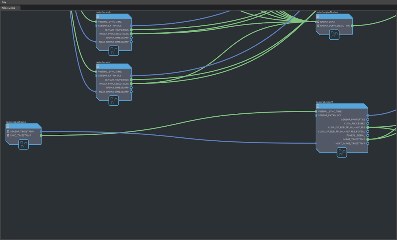
As described earlier, the cameraSensor graphlet contains two nodes, dwCameraNode and ISPNode. By double clicking on the cameraSensor box, a new tab in the GUI tool will be created showing the nodes inside the camera graphlet shown as below:

The division of the processes is defined in CGFDemo.schedule.json file. The processes are divided as the following:
- Camera_master process
- Subcomponents - SelfCalibration, radarSensor0, radarSensor1, radarSensor2, radarSensor3, radarSensor4, radarDopplerMotion, imuSensor, vehicleStateConsumer, vehicleStateConsumer, egomotion, cameraEpochSync, radarEpochSync, imuCanEpochSync
- Render process
- Subcomponents - arender
- Camera_pipeline0 process
- Subcomponents - cameraPipeline0
- Camera_pipeline1 process
- Subcomponents - cameraPipeline1
- Camera_pipeline2 process
- Subcomponents - cameraPipeline2
- Camera_pipeline3 process
- Subcomponents - cameraPipeline3
There are four instances of camera pipelines: cameraPipeline0 - 3. Each pipeline is defined in the CameraPipeline graphlet JSON file. In the CameraPipeline graphlet JSON, it includes three sub-graphlets: CameraSensor, CameraPreProcessingDemo, and CameraObjectDetectorDemo. To view the graphlet in graphical form, you can use the GUI editor tool or simply check the connections section of JSON to determine how the graphlets are connected.
The DNN implementation is based on the sample application "sample_object_detector_tracker". It uses tensorRT_model.bin from the sample app to perform object detection on four 2MP camera recordings. The C++ implementation of this node follows the code structure defined previously in the custom node section.
To render the output of the detection node onto display, an input, CUSTOM_OBJECT_DETECTION_ARRAY, exists in RenderingCGFDemoNode to receive the output of CameraObjectDetectorCGFDemoNode node. The connection takes in an array of detected bounding boxes.
To launch the demo, copy nvsciipc.cfg from targets/<x86_64-Linux or aarch64-Linux>/config/nvsciipc.cfg into /etc/ folder and run script in bin/config/run_cgf.sh. Use the following command to launch the demo:
"sudo ./run_cgf.sh -p /usr/local/driveworks/src/cgf/graphs/descriptions/systems/CGFDemo.system.json -s /usr/local/driveworks/src/cgf/graphs/CGFDemo.stm"I
The default view will show the following:

To view feature tracker rendering, use the following key sequence "nvidia", then 'h' key. To view self-calibration status, press F12 button
Schedule constraints in CGFDemo pipeline
For each pass defined in CGFDemo pipeline to be modeled as an STM runnable, the workload must satisfy the following requirements:
- Each runnable must run on an independent hardware engine. Synchronous workloads are not permitted. They must be reconstituted as CPU runnables that submit another runnable, the async engine workload, to the engine's queue. The runnable that submits the workload is not allowed to wait for the completion of the submitted workload. Instead, another runnable can depend on the submitted workload and can wait for the submitted workload’s completion.
- For each runnable, the following must be specified (please refer to term definitions next page):
- Periodicity (Epoch, Hyperepoch)
- Worst Case Execution Time (WCET)
- Hardware Engine
- Software Resources (if any)
- Process annotation
- Data errors will not be handled by STM. They must be handled by the application's runnables.
In the following, we will take nvidia_computegraphframework_linux-amd64-ubuntu/apps/roadrunner-2.0/graphs/descriptions/systems/CGFDemo.schedule.json as an example for further elaboration.
- Global resources
- Resources that are used system-wide are modeled under the global resources section.
- The CPU, GPU, DLA and VPI resource types are known resource types for the compiler, and it will take specialized scheduling steps for runnables scheduled on those resources. Other resource types are considered as scheduling mutexes, and they do not have any naming restrictions.
{
    "resources": {
        "TegraA": {
            "CPU": ["CPU0", "CPU1", "CPU2", "CPU3", "CPU4", "CPU5"],
            "GPU": ["dGPU"]
        },
        "TegraB": {
        }
    },
    ...
}
- WCET
- "wcet" : "./CGFDemo_wcet.yaml".
- The framework assumes that passes have a bounded runtime. Worst cast of execution time of each pass is defined in CGFDemo_wcet.yaml.
- Hyperepochs
- Hyperepoch is a resource partition that runs a fixed configuration of epochs that share the resources in that partition. It is periodic in nature, and it respawns the contained epochs at the specified period.
"hyperepochs": { "cameraHyperepoch": { "resources": [ "TegraA.CPU0", "TegraA.CPU1", "TegraA.CPU2", "TegraA.CPU3", "TegraA.dGPU", "camera_master.TegraA.CUDA_STREAM0", "camera_master.TegraA.CUDA_MUTEX_LOCK", "camera_pipeline0.TegraA.CUDA_STREAM0", "camera_pipeline0.TegraA.CUDA_MUTEX_LOCK", "camera_pipeline1.TegraA.CUDA_STREAM0", "camera_pipeline1.TegraA.CUDA_MUTEX_LOCK", "camera_pipeline2.TegraA.CUDA_STREAM0", "camera_pipeline2.TegraA.CUDA_MUTEX_LOCK", "camera_pipeline3.TegraA.CUDA_STREAM0", "camera_pipeline3.TegraA.CUDA_MUTEX_LOCK" ], "period": 33000000, "epochs": { "renderEpoch": { "period": 33000000, "frames": 1, "passes": [ "arender" ] }, "cameraEpoch": { "period": 33000000, "frames": 1, "passes": [ "cameraEpochSync", "cameraPipeline0", "cameraPipeline1", "cameraPipeline2", "cameraPipeline3", "selfCalibration" ] }, "radarDopplerMotionEpoch": { "period": 33000000, "frames": 1, "passes": [ "radarDopplerMotion" ] } } }, "imuHyperepoch": { ... } } - Each hyperepoch is associated with a mutually exclusive set of resources. Resources are mapped to hyperepochs by specifying the resource IDs in a list under the ‘Resources’ heading inside the hyperepoch specification.
- The period for a hyperepoch specifies the rate at which the contained epochs are spawned.
- Epochs are timebases at which rate constituent passes spawn confined to the boundaries of the hyperepoch. Each epoch is a member of a hyperepoch, and has two attributes associated with it - Period and Frames.
- Hyperepoch is a resource partition that runs a fixed configuration of epochs that share the resources in that partition. It is periodic in nature, and it respawns the contained epochs at the specified period.
- Processes
- Hyperepochs and epochs define the timing boundaries for tasks (passes). Clients define the data boundaries. A process is an operating system process that contains software resources (like CUDA streams) and passes.
"processes": { "camera_pipeline0": { "executable": "LoaderLite", "subcomponents": [ "cgfDemo.cameraPipeline0", "cgfDemo.arender" ] }, "camera_pipeline1": { "executable": "LoaderLite", "subcomponents": [ "cgfDemo.cameraPipeline1" ] }, "camera_pipeline2": { "executable": "LoaderLite", "subcomponents": [ "cgfDemo.cameraPipeline2" ] }, "camera_pipeline3": { "executable": "LoaderLite", "subcomponents": [ "cgfDemo.cameraPipeline3" ] }, "camera_master": { "executable": "LoaderLite", "subcomponents": [ "cgfDemo.selfCalibration", "cgfDemo.radarSensor0", "cgfDemo.radarSensor1", "cgfDemo.radarSensor2", ... ] } ... } - Clients can specify resources that are visible to passes locally. These resources cannot be accessed by passes in other clients. Global resources are visible to all passes. Process-specific resources like CUDA streams and DLA/VPI handles are some examples of client resources that cannot be shared across different clients. Also, internal scheduling mutexes can also be modeled here.
- In the demo pipeline, there are 6 STM clients (6 operating system processes):
- render
- camera_pipeline0
- camera_pipeline1
- camera_pipeline2
- camera_pipeline3
- camera_master
- Hyperepochs and epochs define the timing boundaries for tasks (passes). Clients define the data boundaries. A process is an operating system process that contains software resources (like CUDA streams) and passes.
NvSciStream channel feature
NvSciStream channel feature in the release, that supports a single producer and a single consumer, is enabled. Some of the channels with a single producer and a single consumer have been updated to NvSciStream in the demo. In graphlet file CGFDemo.graphlet.json, in the connection section, type parameter were changed from socket to nvsci:
"connections": [
    {
        "src": "cameraPipeline0.NEXT_IMAGE_TIMESTAMP",
        "dests": {"cameraEpochSync.SENSOR_TIMESTAMP[0]": {}},
        "params": {"type": "nvsci", "indirect": true}
    },
    ...
]
In addition, nvsciipc.cfg file under directory /etc was modified to add additional ipc slots for NvSciStream to use. Each additional line is a slot allocated for each producer/consumer NvSciStream channel:
INTER_PROCESS cgf_0_p cgf_0_c 16 24576
The naming convention is cgf*<connection number>*<producer/consumer>
Please make sure there are 32 slots allocated inside the nvsciipc.cfg file. After the file has been updated, it is necessary to reboot the system for changes to take effect. To make sure the changes has been properly applied, please check with the following command:
sudo service nv_nvsciipc_init status should print message below:
nv_nvsciipc_init.service - NvSciIpc initialization
Loaded: loaded (/lib/systemd/system/nv_nvsciipc_init.service; enabled; vendor preset: enabled)
Active: inactive (dead) since Wed 2021-06-16 20:36:43 UTC; 52min ago
Process: 758 ExecStart=/bin/sh /etc/systemd/scripts/nv_nvsciipc_init.sh (code=exited, status=0/SUCCESS)
Main PID: 758 (code=exited, status=0/SUCCESS)
If not, please double check your nvsciipc.cfg file.