
GPU Gems 2
GPU Gems 2 is now available, right here, online. You can purchase a beautifully printed version of this book, and others in the series, at a 30% discount courtesy of InformIT and Addison-Wesley.
The CD content, including demos and content, is available on the web and for download.

GPU Gems 2
GPU Gems 2 is now available, right here, online. You can purchase a beautifully printed version of this book, and others in the series, at a 30% discount courtesy of InformIT and Addison-Wesley.The CD content, including demos and content, is available here
Chapter 9. Deferred Shading in S.T.A.L.K.E.R.
Oles Shishkovtsov
GSC Game World
This chapter is a post-mortem of almost two years of research and development on a renderer that is based solely on deferred shading and 100 percent dynamic lighting, targeted at high-end GPUs. Because no single solution can suit all needs, this chapter should not be considered a comprehensive guide to performing deferred shading.
9.1 Introduction
For those who are not familiar with the concepts of deferred shading, we recommend Hargreaves and Harris 2004. This presentation is a good introduction to the basics, and it briefly showcases a number of techniques originally developed for and used in the game S.T.A.L.K.E.R. With deferred shading, during scene-geometry rendering, we don't have to bother with any lighting; instead, we just output lighting properties such as the position and normal of each pixel. Later we apply lighting as a 2D post-process using this intermediate buffer—usually called a G-buffer (Saito and Takahashi 1990)—as input to the lighting shader.
When most people first think about deferred shading, they envision nice algorithmic properties such as perfect depth complexity for lighting, predictable performance proportional to the lights' screen-space areas, simplified scene management, and more. One additional crucial fact is usually missed: the ability to cut down on large numbers of batches, which are inevitable when dynamic shadows come into the game. Ask a representative of your favorite IHV, who will say that many games are still CPU-limited. Reduced CPU usage was one of the main reasons we chose deferred shading in S.T.A.L.K.E.R. Another factor was that forward shading engines (with traditional immediate shading architectures, such as those in Doom 3 or Far Cry) usually unnecessarily pay the high cost of repeating the same work—vertex transform, anisotropic texture filtering, parallax mapping, normal map decompression, detail texturing, and so on. In the case of S.T.A.L.K.E.R., where we were limited both by CPU and by vertex processing and had moderate overdraw, we had almost the ideal case for deferred shading. So, to meet our goal and to raise the visual bar—rendering high-quality, high-polygon content with fully dynamic lighting and shadowing—deferred shading was the inevitable choice. Figures 9-1 and 9-2 show examples of a scene generated by our forward shading and deferred shading renderers, respectively.
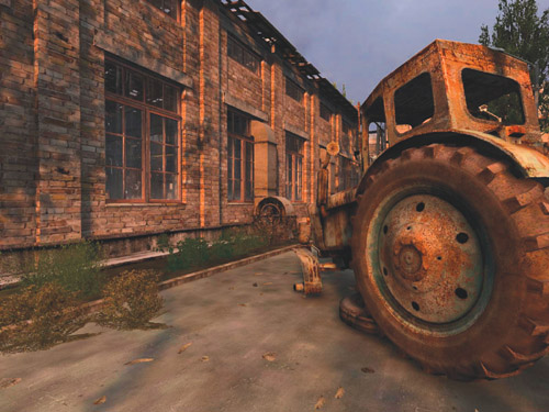
Figure 9-1 Screenshot from the First, Forward Shading Renderer
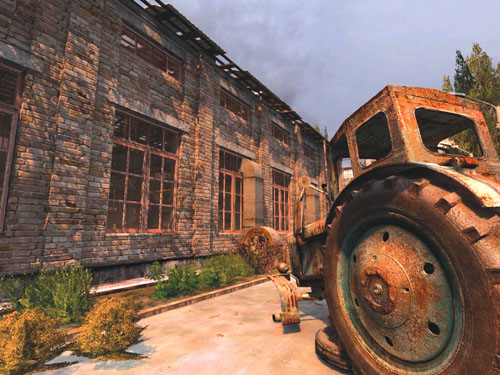
Figure 9-2 Screenshot from the Second, Deferred Shading Renderer
9.2 The Myths
The first myth—"Deferred shading is slow on current hardware"—arises mostly from the fact that the current generation of games tries to load-balance most of the lighting work between the vertex and pixel pipelines. When all the calculations are performed at pixel level (this is the only possible way to go with deferred shading), performance will be similar, because lighting pixel shaders for deferred renderers are not that much more complicated than those for forward renderers. The only added work is G-buffer sampling and, possibly, unpacking. But your application is much less likely to become bottlenecked by the CPU or the vertex pipe. The actual mileage will vary depending on the data set and, more important, on your rendering engine's actual overdraw, measured as the number of pixels passing the z-test divided by the screen area.
Another myth is that deferred shading is useless for rendering directional lights. In S.T.A.L.K.E.R.'s case, this is true for scenes with a few unshadowed directional lights; but it's false even for a single, shadow-casting directional light (such as the sun). A more detailed explanation appears in Section 9.3.2, on the optimization of the lighting phase.
Because deferred renderers process each object only once, conventional techniques for handling multiple material types (such as changing shaders per-object) do not translate well. However, by using DirectX 9 multiple render targets (MRT), we can render up to 16 material attributes during the G-buffer creation phase (four render targets of four floating-point numbers each). Ten are used to perform basic diffuse and specular lighting (three each for albedo, normal, and position, plus one for gloss), but this leaves six components for controlling the lighting functions. In S.T.A.L.K.E.R., we stored material and object IDs in the spare components and defined functions in each light shader (accelerated using 2D and 3D texture lookup tables) that depended on these values. This freed us from a specific material reflection model, while also allowing us to define a huge number of light shader primitives without the combinatorial increase in the number of shaders that affects forward renderers. In addition to the traditional point, spot, and directional light primitives, we also had special light sources such as wrapped hemispherical sources and volumetric fog. This approach can be considered an inversion of the shaders in forward renderers: instead of using light properties to modify material shaders, we used material properties to modify light shaders. By adapting our material system to take advantage of the benefits of deferred shading and using textures to efficiently avoid some of the limitations, we created a deferred rendering engine in which the only limits on the types of materials were the artists' and programmers' imaginations.
During the writing of this chapter, S.T.A.L.K.E.R. was in the process of synchronizing the material look between two renderers: the first one targeted at DirectX 8-class hardware, and a second one targeted at high-end DirectX 9-class hardware. An interesting discovery was that more than 90 percent of materials used in the first renderer were just simple modifiers to the base albedo and emissive terms, plus a few that affected the position and surface normal. Examples are the waving of trees or grass under the wind, or different sorts of detail texturing. These modifications were performed identically in every rendering pass, so there was almost a direct mapping to the forward phase of the second renderer, the G-buffer creation phase.
9.3 Optimizations
Delivering a product that pushes the newest graphics hardware to its limits while still offering a playable game requires a great deal of planning. Both technical and artistic decisions must consider the target audience and the target hardware. Failing to do so may result in significant wasted effort. This happened to us when we changed the target for S.T.A.L.K.E.R.'s first renderer from fixed-function T&L (DirectX 7-class) GPUs to first-generation pixel shading (DirectX 8-class) GPUs; we had to rewrite much of our tool set and engine to accommodate the change. Our goals for S.T.A.L.K.E.R.'s second (deferred) renderer were for it to be a drop-in replacement for the first renderer (so it would work on the same data set and content, except for the lighting environment), and for it to run with "maximal eye candy" at 30 frames per second on a GeForce 6800 Ultra at 1024x768 resolution. We encouraged our designers to complicate the second renderer's lighting environment whenever the performance exceeded this target.
9.3.1 What to Optimize
Given the structure of a deferred renderer, the obvious places that are likely to be performance bottlenecks are deferring, lighting, and post-processing. Our S.T.A.L.K.E.R. performance testing confirmed this:
- Average number of lights per frame in closed spaces: 50
- Average number of lights per pixel in closed spaces: 5
- Average number of lights per pixel in open spaces: less than 1
- Average geometric depth complexity: 2.5
Because one of the primary features of the second renderer is real-time shadowing, shadow creation was a significant bottleneck; in fact, in some scenes it turned out to be the largest individual bottleneck. Given this, our optimization goals were obvious:
- Limit the number of lights drawn to just those that affect the rendered image.
- Convert shadow-casting lights to unshadowed lights where possible.
- Simplify the lighting shaders as much as possible.
- Optimize post-processing and deferring passes, but not at the expense of quality.
We decided to favor quality over performance for the G-buffer creation and post-processing (G-buffer shading) passes because these have tightly bounded costs, whereas a game player is free to drop multiple torches in the same place, making lighting arbitrarily expensive. Also, most artists are comfortable optimizing for forward renderers (by reducing the number of polygons or the resolution of textures, adding good occluders, and so on), and these optimizations also benefit the deferring pass.
9.3.2 Lighting Optimizations
The most important optimization for the lighting pass is to render only those lights that actually affect the final image, and for those lights, render only the affected pixels. For S.T.A.L.K.E.R., we used a hierarchical occlusion-culling system that utilized both the CPU and the GPU. Our coarsest test was sector-portal culling followed by CPU-based occlusion culling (similar to the hierarchical z-buffer [Greene et al. 1993]). In a typical closed-space frame, this reduced the number of lights by up to 30 to 50 percent. Then we used DirectX 9's occlusion query to eliminate the completely occluded lights. Finally, we used a stencil mask to tag affected pixels for each light. All together, these culling optimizations resulted in a twofold or even larger performance increase.
Even with perfect culling, though, lighting is still the most expensive aspect of a deferred renderer. Therefore, it is important to make sure that the shaders and artistic properties of the light sources are optimized as much as possible. About half of the time we spent creating S.T.A.L.K.E.R.'s deferred renderer was devoted to searching for ways to squeeze additional cycles out of our lighting shaders. The primary artistic decisions we made were these:
-
Does the light need to cast shadows?
– Many lights are needed only to mimic a global illumination-style look, and shadows just ruin the illusion.
-
Does the light need a projective image?
– If so, maybe the projection is the same as the shadow-map projection (which saves a few dp4s)?
-
Does the light need to cast shadows from translucent surfaces? See Figure 9-3.
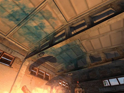
Figure 9-3 Cast Shadows from Translucent Objects
– If so, are there any translucent surfaces that exist in the light's frustum?
– If both projective image and translucent color-modifier are required, maybe we can combine them into one image?
-
Does the light need to contribute to glossy specular reflection?
– Many lights in S.T.A.L.K.E.R. were added to mimic global illumination. For these lights, we used very simple diffuse-only lighting.
-
Does the light move?
– If it doesn't, we precomputed shadow-caster visibility to make shadow generation more efficient, by incrementally testing visibility for primitives that are found to be static to each other in a particular light configuration, thus forming a conservative potentially visible set (PVS) with a set of rules that can invalidate parts of it.
Additionally, we made some special optimizations for directional lights (such as the sun).
Optimizing the Sun
Although large-scale shadow mapping from directional light sources is a quite interesting and difficult problem, it is beyond the scope of this chapter. We used a single 2048 x 2048-pixel shadow map for most of the sun lighting, using a perspective shadow map-style projection transform to maximize area near the viewer. A demo showcasing a variety of related techniques can be found in King 2004. Sun shadows need very careful filtering and therefore have a relatively high per-pixel cost, so we want to skip as much work as possible; this is where deferred shading comes in. The first optimization comes from the fact that the sky box doesn't need to be shaded, and it occupies a significant part of the screen (30 to 40 percent is common in a typical outdoor environment). Also, in average configurations of the viewer and sun direction, approximately 50 percent of pixels face away from the sun and don't need to have complex shading applied. Finally, the pixels that have an ambient occlusion term of zero cannot be reached by sun rays, so they can also be excluded from processing. We use a shader to quickly determine these conditions per-pixel, and store the results in a stencil mask so that the GPU's hierarchical culling hardware can avoid applying complex shading on these pixels.
The final algorithm for sunlight accumulation is shown in Listing 9-1.
Note: There is an option to use a single-sample shadow term in pass 0 to avoid the lighting and shadow filtering cost for points in shadow. This doesn't work in practice because (1) the performance was lower, and (2) a single sample is insufficient, because the percentage-closer filtering (PCF) kernel in pass 1 is quite large.
This idea is more useful for Pixel Shader 3.0 dynamic branching, because it has high screen-space coherence and because these shadow samples can be utilized in the final computation. This is left as an exercise for the reader.
We can compute the theoretical performance increase due to this stencil mask: assuming that 15 percent of pixels have an ambient occlusion of zero, and 30 percent of the frame is occupied by the sky, the expected percentage of pixels that will be shaded is (1 - 0.3) x 0.5 x (1 - 0.15)  30 percent, or about a 3x increase in frames per second. The actual performance increase measured in S.T.A.L.K.E.R. was close to 2x.
Example 9-1. Pseudocode for Sunlight Accumulation
Pass 0 : Render full - screen quad only where 0x03 ==
    stencil count(where attributes are stored)
        If((N dot L)*ambient_occlusion_term >
           0) discard fragment Else color = 0,
                                    stencil = 0x01 Pass 1
    : Render full
      -
      screen quad only where
      0x03 == stencil count Perform light accumulation / shading
9.3.3 G-Buffer-Creation Optimizations
The biggest individual step you can take to improve the performance of creating the G-buffer is selecting the appropriate format for the buffer itself.
Contrary to a common misconception, you don't need a feature-rich GPU to do deferred shading. All you need is DirectX 9 Pixel Shader 2.0 support; no fancy surface formats or even MRT are strictly required. All of these extras can be considered optimizations for performance and quality. Implementations exist for other platforms as well, such as the Microsoft Xbox and the Sony Playstation 2 (Geldreich et al. 2004).
First we have to define the space in which we work. Due to the limited range of components, we are forced to work in a tight, restricted space. The obvious candidates are view space and post-projection space. Then comes the question: How much performance can we dedicate to unpacking?
The drawback of any fat-format encoding (that is, having buffers larger than 32 bits per texel) is the reading speed. For example, a 64-bit texel can take twice as much time to load as a 32-bit one, even when the entire surface fits inside the texture cache (and 128-bit texels are even slower).
So let's start with the assumption (which is not the case, in fact) that we are limited by MRT surface count. We outline the major features of the most practical solutions first for position encoding and then for normal encoding. See Table 9-1.
Table 9-1. Storage Options for the Position Buffer
|
Depth Only (32 bits per pixel) |
Full (x, y, z) Position (64 bits per pixel) |
|||
|
R32F |
A8R8G8B8 |
Post-Projection Space |
Eye Space |
|
|
Hardware Support |
GeForce FX or better |
All |
GeForce FX or better |
GeForce FX or better |
|
Radeon 9500 or better |
Radeon 9500 or better |
Radeon 9500 or better |
||
|
G-Buffer Creation Cost |
Single mov |
Three texs |
One rcp |
Single mov |
|
Low bandwidth |
Three muls |
One mul |
||
|
One mov |
One mov |
|||
|
Decoding Cost |
One mov |
Same as the R32F, plus one dp3 |
Four dp4s |
None |
|
Four dp4s |
One rcp |
|||
|
One rcp |
One mul |
|||
|
One mul for screen-space reconstruction Similar cost for ray-based reconstruction |
||||
|
Sampling and Storage |
32 bits |
32 bits |
64 bits |
64 bits |
|
Virtual Position Support |
Limited |
Limited |
Arbitrary, but expensive |
Arbitrary |
|
Free Components |
0 |
1 |
1 |
1 |
Depth encoding is usually done in one of two ways:
- Storing z/w of the visible surface at each pixel. Along with the (x, y) pixel coordinates and information from the perspective projection, this is enough information to reconstruct the 3D eye-space position.
- Storing distance from the near plane, thus avoiding the division in the G-buffer-creation phase. Along with interpolated ray direction (from the eye position to the center of the pixel on the near plane), this is enough to find the exact point of intersection.
There is no row labeled "Precision of the Method" in Table 9-1 because the methods are all similar in this respect. There may be differences due to hardware precision, but assuming fp32-capable hardware, we can build the following list, from best to worst:
- Depth, encoded as R32F (single-component, 32-bit floating point)
- Post-projection space, integer encoding, all three components (x, y, z) stored
- Depth, encoded in 24-bit R8G8B8
- Eye-space, fp16 encoding, all three components (x, y, z) stored
This ordering depends, of course, on the application, but the differences are not significant enough to worry about in a typical open-space, first-person shooter view.
The options for storing the normals (stored in eye space, which has obvious benefits for lighting calculations) are shown in Table 9-2.
Table 9-2. Storage Options for the Normal Buffer
|
A8R8G8B8 |
A2R10G10B10 |
R16G16F |
A16R16G16B16F |
|
|
Hardware Support |
All |
Radeon 9500 or better |
GeForce FX or better |
GeForce FX or better |
|
Radeon 9500 or better |
Radeon 9500 or better |
|||
|
Deferring Cost |
One mad |
One mad |
None |
None |
|
Decoding Cost |
One mad |
One mad |
One mov |
None |
|
One nrm |
One nrm |
One dp2a |
||
|
One rsq |
||||
|
One rcp |
||||
|
Sampling and Storage |
32 bits |
32 bits |
32 bits |
64 bits |
|
Quality |
Poor |
Good for rough surfaces |
Excellent |
Excellent |
|
Free Components |
1 |
1 |
0 |
1 |
|
Very low precision |
Interestingly enough, S.T.A.L.K.E.R. was actually working using each of the encodings shown in Table 9-2 at different times during development, and on quite different hardware, with combinations limited only by the fact that rendering targets must have the same bit depth on current hardware when using MRT. The only interesting exception was the NVIDIA GeForce FX line of GPUs, where deferring was performed via DirectX 9 multi-element textures (MET), instead of multiple render targets, but was then decompressed into ordinary surfaces, mostly because of sampling performance and latency issues.
We can make quality and performance trade-offs using the options enumerated in these tables and some basic renderer statistics. Because many lights affect every pixel in S.T.A.L.K.E.R., sampling and decoding affects performance more than any other properties. On the other hand, the quality of the stored normals, and the ability to support virtual position (more about this later) greatly influence the resulting image quality. Free components can be used to improve performance, too, but only in limited cases.
In addition to position and normal, S.T.A.L.K.E.R.'s pipeline required three other attributes: gloss mask, an ambient occlusion term, and material index. The ideal configuration for us became: material (FX8), ambient-occlusion (FX8), gloss-mask (FX8), position (3xFP16), and normal (3xFX16). The closest configuration we were able to achieve, using DirectX-supported formats, was eye-space position and ambient occlusion stored in A16R16G16B16F, eye-space normal and material ID stored in another A16R16G16B16F, and RGB albedo and gloss stored in A8R8G8B8. Because of a limitation of current graphics hardware that requires the same bit depth for surfaces used in the MRT operation, the albedo-gloss surface was expanded to full A16R16G16B16F. This encoding could be seen as a waste of video memory bandwidth—and it is indeed. However, this "wasteful" configuration was actually the fastest on a GeForce 6800 Ultra, even when compared to smaller, lower-quality alternatives, because of its much simpler decoding. That is why S.T.A.L.K.E.R. dropped support for any other layout, although we do check for MRT_INDEPENDENT_BITDEPTH to try to utilize a 32-bit format for albedo and gloss, even if no hardware capable of doing so currently exists in the market.
9.3.4 Shadowing Optimizations
Stencil shadows and shadow maps both work well within deferred renderers. For artistic reasons, we chose to use shadow maps exclusively in S.T.A.L.K.E.R. This allowed us to cast shadows from semitransparent geometry and adjust the shadow boundary based on each pixel's virtual position. However, most important, we were able to generate smooth, soft shadow transitions, which is not possible with stencil shadows.
We implemented only the basic types of shadowed light sources, because highly specialized implementations allowed us to optimize them greatly. The next section briefly touches on spotlights, but our main focus is on omnidirectional lights, which are the most difficult light sources from which to cast shadows, especially if you're concerned about performance.
Efficient Omni Lights
There are three major options for omnidirectional shadow mapping in deferred renderers:
- Using a cube map for storing distance from the light center, R32F or A8R8G8B8 packed.
- Using a 2D surface with "unrolled" cube-map faces, with reindexing done through a small cube map (called virtual shadow depth cube texture [King and Newhall 2004]).
- Treating the point light as six spotlights and rendering each separately.
There is another technique, called "dual-paraboloid shadow maps," but it is not generally applicable to deferred shading, because a nonlinear projection applied first at the vertex level and then at the pixel level can lead to major artifacts.
Let's outline the major benefits and drawbacks, as shown in Table 9-3. Here, by scalability we mean using different sizes for different faces, which can enable packing shadow maps for many lights on one surface. Continuity means we are able to change the resolution smoothly from, say 1024 x 1024 to 16 x 16 in one-pixel decrements.
Table 9-3. Comparison of Omni Lighting Techniques
|
Cube Map |
Virtual Shadow Depth Cube Texture |
Six Spotlights |
|
|
Scalability and Continuity |
Low Few fixed sizes All faces are the same |
Moderate Faces can be of different sizes, but only from a few fixed sets |
Excellent Any variation of sizes is possible |
|
Hardware Filtering Support |
No |
Yes |
Yes |
|
Cost of Filtering |
Moderate |
Excellent for bilinear Moderate for arbitrary percentage-closer filtering |
Excellent |
|
Render Target Switches |
Six |
One |
One |
|
Packing Support |
No |
Yes |
Yes |
|
Cost of Screen Space Stencil Masking |
Low |
Low |
Moderate Some stencil overdraw |
|
Memory Cost and Bandwidth Usage |
High Surface is almost unusable for everything else |
Moderate Few fixed sizes limits packing ability |
Excellent |
Treating point lights like six spotlights is difficult for forward shading engines due to the amount of retransformed geometry for every face, but for deferred shading, it is probably the best choice. S.T.A.L.K.E.R. was doing a lot of shadow-filtering work, so that was the option we chose. One nuance to keep in mind: leave a small border around each spotlight (small, but larger than the filter-kernel radius) to avoid filtering glitches at frustum edges.
9.4 Improving Quality
The architecture of a deferred renderer can greatly affect the final image quality, as can the decisions made on what to store in the G-buffer. This section briefly outlines a few decisions and tricks we used in S.T.A.L.K.E.R. to achieve the level of visual quality we needed.
9.4.1 The Power of "Virtual Position"
Simulated displacement mapping is extremely popular in next-generation engines. (See Chapter 8 of this book, "Per-Pixel Displacement Mapping with Distance Functions," for a related technique.) The simplest (and most popular) of these approaches is parallax mapping (Kaneko et al. 2001, Welsh 2004). It works reasonably well with most lighting models, except when it comes to shadows. It looks really strange when the shadows are still, but the underlying surface changes due to different eye position or lighting conditions. Our trick to hide such objectionable effects was to move the eye-space position slightly away from the surface in the direction of the per-pixel normal, in proportion to the height map value at the original sampling point, as shown in Figures 9-4 and 9-5. Doing so adds a greater sense for the bumpiness of the surface close to shadow boundaries or really close to light sources. Another, unintended, effect of this trick was alleviating most of the biasing problems associated with shadow maps. The reason why this works is simple: with good filtering, the worst "surface acne" appears in areas with low heights—which is almost desirable, because in real life, pits are usually darker from self-occlusion.
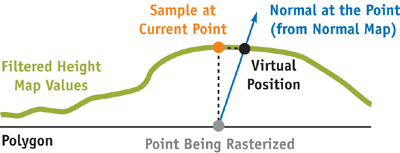
Figure 9-4 The Virtual Position Trick
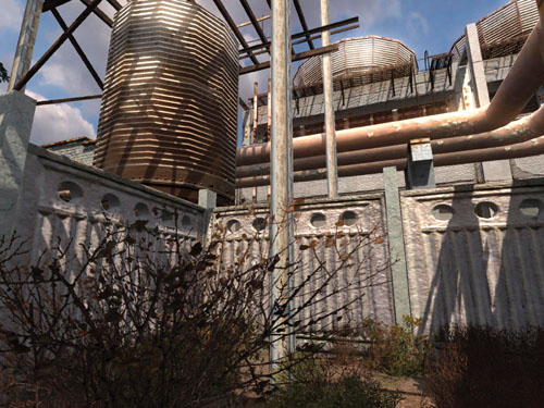
Figure 9-5 The Virtual Position Trick in Action
9.4.2 Ambient Occlusion
Our most ambitious goal in writing S.T.A.L.K.E.R.'s second renderer was to create a purely dynamic renderer that didn't depend on any precalculation, especially for the lighting environment. We met the goal, with two exceptions:
- The sector-portal structure and low-polygonal geometry used for occlusion culling was already available from the data set created for the first renderer.
- The ambient occlusion term was available too, but it was stored mostly in light maps, used by the first renderer.
Using visibility data may seem like a compromise, but this data doesn't require much preprocessing (we don't use any sort of PVS and mostly rely on occlusion culling). On the other hand, using light maps for the ambient occlusion term seemed to be a big waste of both memory and designer time. Instead, we stored the occlusion term in an unused per-vertex component, and this worked well enough for S.T.A.L.K.E.R. The way we handle it: tessellating original geometry up to a constant edge length (0.5 meters in our case), then applying adaptive tessellation, estimating both edge error and the triangle-middle-point error up to a minimum edge length (0.1 meters in our case). The next step was simplification based on the Quadric Error Metric algorithm (see Garland and Heckbert 1998 and Hoppe 1999) with intermediate errors recomputed at each iteration with a simple placement policy of three variants: edge middle, first, or second vertex. We allow no more than a 10 percent increase in vertex count and use a fixed maximal error limit, but in practice we did not reach this limit on vertices in any of our levels. Although we still allowed the usage of light maps to store the ambient occlusion term, we encouraged our artists to shift to a vertex-based solution. The result: our first renderer was changed to use the vertex-based ambient occlusion, too.
9.4.3 Materials and Surface-Light Interaction
The generic way of doing materials in a deferred renderer—store all the information the light-shader needs—is the right way to go in the future, because "Hey! The real world is shaded by the same shader." The alternative is to use something like material index and to apply different fragment programs to different materials branching on this index—this is fairly questionable on today's hardware though.
To maintain the target frame rate, we limited ourselves to a material index into a light-response lookup table. After many experiments to find an optimal re-parameterization for this texture, we settled on the simplest and most intuitive way: indexing the volume texture by (N · L, N · H, material). This allows a fairly large range of materials to be simulated, from dimmed surfaces to glossy reflecting ones, and even a faux-anisotropic reflection model. Figure 9-6 shows an example.
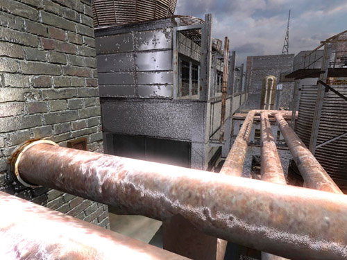
Figure 9-6 Metallic Material Forced for All Surfaces
The beauty of this solution is that materials that come from adjacent layers in the texture can be blended by the texture-sampling unit for free. We also discovered that when the layers are ordered by increasing shininess (or decreasing roughness), we needed only four layers to represent almost everything in S.T.A.L.K.E.R. So, the result was a 64 x 256 x 4, A8L8 texture summing up to a 128 K table with fairly coherent access from the pixel shader. We left the diffuse lookup at this relatively high resolution (64 samples), because the function it stores may not be linear, and linear filtering that is done by hardware isn't always acceptable.
9.5 Antialiasing
A deferred renderer is just incompatible with current hardware-assisted antialiasing, unfortunately (Hargreaves and Harris 2004). Thus, antialiasing becomes solely the responsibility of the application and the shader; we cannot rely on the GPU alone. Because aliasing itself arises from the mismatched frequencies of the source signal and of the destination discrete representation, a good approximation of an antialiasing filter is just a low-pass filter, which is simple blurring. This is a zero-cost operation in the console world, where any TV display works like a low-pass filter anyway. In the PC world, we need an alternative. Our solution was to trade some signal frequency at the discontinuities for smoothness, and to leave other parts of the image intact. This was performed in a way similar to the edge-detection filters used in nonphotorealistic applications: We detect discontinuities in both depth and normal direction by taking 8+1 samples of depth and finding how depth at the current pixel differs from the ideal line passed through opposite corner points. The normals were used to fix issues such as a wall perpendicular to the floor, where the depth forms a perfect line (or will be similar at all samples) but an aliased edge exists. The normals were processed in a similar cross-filter manner, and the dot product between normals was used to determine the presence of an edge. Listing 9-2 shows the code.
The two detectors were then multiplied to produce a single value indicating how much the current pixel "looks like an edge." This value was used to offset four bilinear texture lookups into the composited (near-final) back buffer. The result was automatic weighting of samples with a very strong edge-detection policy that seamlessly handles edge and alpha-test/texkill aliasing without blurring other parts of the image. See Figure 9-7 for a sample result.
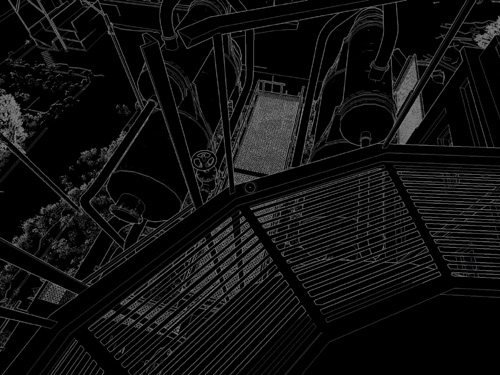
Figure 9-7 Weight Computed by the Edge-Detection Shader
Example 9-2. Edge-Detection Shader Used for Antialiasing
struct v2p
{
  float4 tc0 : TEXCOORD0; // Center
  float4 tc1 : TEXCOORD1; // Left Top
  float4 tc2 : TEXCOORD2; // Right Bottom
  float4 tc3 : TEXCOORD3; // Right Top
  float4 tc4 : TEXCOORD4; // Left Bottom
  float4 tc5 : TEXCOORD5; // Left / Right
  float4 tc6 : TEXCOORD6; // Top / Bottom
};
/////////////////////////////////////////////////////////////////////
uniform sampler2D s_distort;
uniform half4 e_barrier;
// x=norm(~.8f), y=depth(~.5f)
uniform half4 e_weights;
// x=norm, y=depth
uniform half4 e_kernel;
// x=norm, y=depth
/////////////////////////////////////////////////////////////////////
half4 main(v2p I) : COLOR
{
  // Normal discontinuity filter
  half3 nc = tex2D(s_normal, I.tc0);
  half4 nd;
  nd.x = dot(nc, (half3)tex2D(s_normal, I.tc1));
  nd.y = dot(nc, (half3)tex2D(s_normal, I.tc2));
  nd.z = dot(nc, (half3)tex2D(s_normal, I.tc3));
  nd.w = dot(nc, (half3)tex2D(s_normal, I.tc4));
  nd -= e_barrier.x;
  nd = step(0, nd);
  half ne = saturate(dot(nd, e_weights.x));
  // Opposite coords
  float4 tc5r = I.tc5.wzyx;
  float4 tc6r = I.tc6.wzyx;
  // Depth filter : compute gradiental difference:
  // (c-sample1)+(c-sample1_opposite)
  half4 dc = tex2D(s_position, I.tc0);
  half4 dd;
  dd.x = (half)tex2D(s_position, I.tc1).z + (half)tex2D(s_position, I.tc2).z;
  dd.y = (half)tex2D(s_position, I.tc3).z + (half)tex2D(s_position, I.tc4).z;
  dd.z = (half)tex2D(s_position, I.tc5).z + (half)tex2D(s_position, tc5r).z;
  dd.w = (half)tex2D(s_position, I.tc6).z + (half)tex2D(s_position, tc6r).z;
  dd = abs(2 * dc.z - dd) - e_barrier.y;
  dd = step(dd, 0);
  half de = saturate(dot(dd, e_weights.y));
  // Weight
  half w = (1 - de * ne) * e_kernel.x; // 0 - no aa, 1=full aa
  // Smoothed color
  // (a-c)*w + c = a*w + c(1-w)
  float2 offset = I.tc0 * (1 - w);
  half4 s0 = tex2D(s_image, offset + I.tc1 * w);
  half4 s1 = tex2D(s_image, offset + I.tc2 * w);
  half4 s2 = tex2D(s_image, offset + I.tc3 * w);
  half4 s3 = tex2D(s_image, offset + I.tc4 * w);
  return (s0 + s1 + s2 + s3) / 4.h;
}
There is one side note to this approach: the parameters/delimiters tweaked for one resolution do not necessarily work well for another; even worse, they often do not work at all. That is because the lower the resolution, the more source signal is lost during discretization, and blurring becomes a worse approximation of an antialiasing filter. Visually, you get more and more false positives, and the picture becomes more blurred than necessary. However, lowering the blur radius according to resolution works fine.
9.5.1 Efficient Tone Mapping
Both high-dynamic-range lighting and automatic exposure control are natural, easy, and relatively cheap extensions to deferred renderers. But the way S.T.A.L.K.E.R. handles this is somewhat different.
The main difference is that we estimate scene luminance based only on the luminance of a blurred bloom surface. So the desired luminance should be set really low, to something like 0.01.
When building the bloom target, we blend information from the current frame into the previous frame's bloom target. This gives sharper highlights near the really bright parts and allows use of a smaller filter kernel; we used a simple 2 x 2 cross filter. The side effect of this approach is the appearance of a slight motion blur, but this was even desired by our artists.
After the final average luminance was determined, we blended it into a 1 x 1 R32F render target to perform adaptation (as in the DirectX 9 SDK sample); however, the blend speed needed to be significantly lower than the bloom's blend speed to avoid resonance effects.
Our initial implementation used the classical tone-map operator similar to the log-average one described in the DirectX SDK. We changed this to a simple linear scale and linear average luminance estimation, because our artists complained that the original one reduced contrast. This works better for us because our data set was designed around the low-dynamic-range rendering used in the first renderer.
The result is spectacular and extremely efficient: enabling tone mapping with automatic exposure control has less than a 1 percent impact on frame rate.
9.5.2 Dealing with Transparency
Unfortunately, deferred renderers are incompatible with any sort of alpha blending. Depth peeling (Everitt 2001) is not an option, given current GPU performance levels. [1] We handled transparency with a straightforward hack: we used forward rendering for transparent primitives with lighting but without shadows. This was done by copying-and-pasting from the first renderer's source tree.
9.6 Things We Tried but Did Not Include in the Final Code
Because of our goal to raise the visual bar higher than any game ever written, even without deep content modification (content was almost fixed at the time of writing, except for constant small changes required by gameplay flow), we tried a few ideas that didn't make it into the actual commercial game.
9.6.1 Elevation Maps
The concept of elevation maps can be found in Dietrich 2000. The first assumption was that because the layers are drawn only in the first (attribute-deferring) phase, they should not greatly affect performance. Another assumption was that with little position modification (perhaps 1 cm total), we should be able to hide layering with a relatively small number of layers, something like three to five layers.
After implementation of this scheme, we found the following:
- To make 1 cm of displacement, we need at least 32 layers at 1024 x 768 resolution, so that layering becomes invisible, but even then, the algorithm fails around the sharp edges, where it produces something like "fur."
- Deferring even 4 layers costs an incredible amount of fill and shading power (especially including texkill, which can work against early-z), dropping the frame rate by up to 30 percent.
- The antialiasing method described earlier proved to be quite good at masking out artifacts between layers.
Although we decided to drop the scheme altogether, it was fun to see adaptive displacement mapping in almost real time, approximately 3 frames per second with 64 layers. The idea can still be useful for an application with a cheaper G-buffer creation phase.
9.6.2 Real-Time Global Illumination
An old dream for the author of this chapter was to see global illumination in an interactive application, which doesn't depend on any precomputation and works with 100 percent dynamic lighting conditions and a similarly dynamic environment. The algorithm we chose is similar to photon mapping (Jensen 2001), but without any sort of "final gathering." (Although not strictly related, one may want to read a paper of Ingo Wald's, such as Wald 2003.) All the lights were modified to track the changes in their local environment by casting hundreds of rays (on the CPU) in random directions; selecting the fixed amount of the brightest secondary, indirect lights; adding them to the database; and then repeating the same process on them until the minimal threshold was reached or the fixed number of iterations ended. Then everything continued as usual, up to the end of render-frame, where all the secondary lights were just destroyed (cached, in fact).
The first results were at least strange from a visual standpoint: lots of bright spots everywhere, crossed by weird shadows. Then the secondary light was modified to be more like a hemispherical spot, with the major contribution along the primary axis (parent reflection vector) and gradually lowering power to the sides. The shadows were disabled altogether, but CPU-based rays were increased several times to provide some sense of occlusion. For the sake of optimization, the specular contribution from the secondary lights was dropped; also the lights used no material information at all—they were pure Blinn-style. The result really looks like a global illumination and was obtained almost in real time: up to 10 frames per second with up to 500 indirect lights, where direct-only lighting runs at around 50 to 60 frames per second on our target hardware.
Although this frame rate is unacceptable for a real-time game application, one can extrapolate the performance growth curve of current GPUs—approximately doubling in performance every year—to hope that in two years, this approach could be practical.
9.7 Conclusion
Deferred shading, although not appropriate for every game, proved to be a great rendering architecture for accomplishing our goals in S.T.A.L.K.E.R. It gave us a rendering engine that leverages modern GPUs and has lower geometry-processing requirements, lower pixel-processing requirements, and lower CPU overhead than a traditional forward shading architecture. And it has cleaner and simpler scene management to boot. Once we worked around the deficiencies inherent in a deferred shader, such as a potentially restricted material system and the lack of antialiasing, the resulting architecture was both flexible and fast, allowing for a wide range of effects. See Figure 9-8 for an example. Of course, the proof is in the implementation. In S.T.A.L.K.E.R., our original forward shading system, despite using significantly less complex and interesting shaders, actually ran slower than our final deferred shading system in complex scenes with a large number of dynamic lights. Such scenes are, of course, exactly the kind in which you need the most performance!
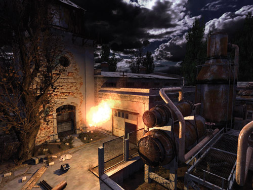
Figure 9-8 in Action
9.8 References
Dietrich, Sim. 2000. "Elevation Maps." http://www.nvidia.com/object/Elevation_Maps_Paper.html
Everitt, C. 2001. "Interactive Order-Independent Transparency." NVIDIA technical report. http://developer.nvidia.com/object/Interactive_Order_Transparency.html
Foley, James D., Andries van Dam, Steven K. Feiner, and John F. Hughes. 1990. Computer Graphics: Principles and Practice. Addison-Wesley.
Garland, M., and P. Heckbert. 1998. "Simplifying Surfaces with Color and Texture Using Quadric Error Metrics." In IEEE Visualization 98, October 1998, pp. 263–269.
Geldreich, Rich, Matt Pritchard, and John Brooks. 2004. "Deferred Lighting and Shading." Presentation at Game Developers Conference 2004. http://www.gdconf.com/archives/2004/pritchard_matt.ppt
Greene, Ned, Michael Kass, and Gavin Miller. 1993. "Hierarchical Z-Buffer Visibility." In Computer Graphics (Proceedings of SIGGRAPH 93), pp. 231–238.
Hargreaves, Shawn, and Mark Harris. 2004. "Deferred Shading." Presentation. http://download.nvidia.com/developer/presentations/2004/6800_Leagues/6800_Leagues_Deferred_Shading.pdf
Hoppe, H. 1999. "New Quadric Metric for Simplifying Meshes with Appearance Attributes." In IEEE Visualization 99, October 1999, pp. 59–66.
Jensen, Henrik Wann. 2001. Realistic Image Synthesis Using Photon Mapping. AK Peters.
Kaneko, Tomomichi, Toshiyuki Takahei, Masahiko Inami, Naoki Kawakami, Yasuyuki Yanagida, Taro Maeda, and Susumu Tachi. 2001. "Detailed Shape Representation with Parallax Mapping." In Proceedings of the ICAT 2001 (The 11th International Conference on Artificial Reality and Telexistence), Tokyo, December 2001, pp. 205–208.
King, Gary. 2004. Practical Perspective Shadow Mapping demo. http://download.nvidia.com/developer/SDK/Individual_Samples/DEMOS/Direct3D9/PracticalPSM.zip
King, Gary, and William Newhall. 2004. "Efficient Omnidirectional Shadow Maps." In ShaderX 3, edited by Wolfgang Engel. Charles River Media.
Saito, T., and T. Takahashi. 1990. "Comprehensible Rendering of 3-D Shapes." In Computer Graphics (Proceedings of SIGGRAPH 90) 24(4), August 1990, pp. 197–206.
Wald, Ingo. 2003. Instant Global Illumination, Version II. http://www.openrt.de/Gallery/IGI2/
Welsh, Terry. 2004. "Parallax Mapping with Offset Limiting: A Per-Pixel Approximation of Uneven Surfaces." http://www.infiscape.com/doc/parallax_mapping.pdf
Copyright
Many of the designations used by manufacturers and sellers to distinguish their products are claimed as trademarks. Where those designations appear in this book, and Addison-Wesley was aware of a trademark claim, the designations have been printed with initial capital letters or in all capitals.
The authors and publisher have taken care in the preparation of this book, but make no expressed or implied warranty of any kind and assume no responsibility for errors or omissions. No liability is assumed for incidental or consequential damages in connection with or arising out of the use of the information or programs contained herein.
NVIDIA makes no warranty or representation that the techniques described herein are free from any Intellectual Property claims. The reader assumes all risk of any such claims based on his or her use of these techniques.
The publisher offers excellent discounts on this book when ordered in quantity for bulk purchases or special sales, which may include electronic versions and/or custom covers and content particular to your business, training goals, marketing focus, and branding interests. For more information, please contact:
U.S. Corporate and Government Sales
(800) 382-3419
corpsales@pearsontechgroup.com
For sales outside of the U.S., please contact:
International Sales
international@pearsoned.com
Visit Addison-Wesley on the Web: www.awprofessional.com
Library of Congress Cataloging-in-Publication Data
GPU gems 2 : programming techniques for high-performance graphics and general-purpose
computation / edited by Matt Pharr ; Randima Fernando, series editor.
p. cm.
Includes bibliographical references and index.
ISBN 0-321-33559-7 (hardcover : alk. paper)
1. Computer graphics. 2. Real-time programming. I. Pharr, Matt. II. Fernando, Randima.
T385.G688 2005
006.66—dc22
2004030181
GeForce™ and NVIDIA Quadro® are trademarks or registered trademarks of NVIDIA Corporation.
Nalu, Timbury, and Clear Sailing images © 2004 NVIDIA Corporation.
mental images and mental ray are trademarks or registered trademarks of mental images, GmbH.
Copyright © 2005 by NVIDIA Corporation.
All rights reserved. No part of this publication may be reproduced, stored in a retrieval system, or transmitted, in any form, or by any means, electronic, mechanical, photocopying, recording, or otherwise, without the prior consent of the publisher. Printed in the United States of America. Published simultaneously in Canada.
For information on obtaining permission for use of material from this work, please submit a written request to:
Pearson Education, Inc.
Rights and Contracts Department
One Lake Street
Upper Saddle River, NJ 07458
Text printed in the United States on recycled paper at Quebecor World Taunton in Taunton, Massachusetts.
Second printing, April 2005
Dedication
To everyone striving to make today's best computer graphics look primitive tomorrow
- Copyright
- Inside Back Cover
- Inside Front Cover
- Part I: Geometric Complexity
-
- Chapter 1. Toward Photorealism in Virtual Botany
- Chapter 2. Terrain Rendering Using GPU-Based Geometry Clipmaps
- Chapter 3. Inside Geometry Instancing
- Chapter 4. Segment Buffering
- Chapter 5. Optimizing Resource Management with Multistreaming
- Chapter 6. Hardware Occlusion Queries Made Useful
- Chapter 7. Adaptive Tessellation of Subdivision Surfaces with Displacement Mapping
- Chapter 8. Per-Pixel Displacement Mapping with Distance Functions
- Part II: Shading, Lighting, and Shadows
-
- Chapter 9. Deferred Shading in S.T.A.L.K.E.R.
- Chapter 10. Real-Time Computation of Dynamic Irradiance Environment Maps
- Chapter 11. Approximate Bidirectional Texture Functions
- Chapter 12. Tile-Based Texture Mapping
- Chapter 13. Implementing the mental images Phenomena Renderer on the GPU
- Chapter 14. Dynamic Ambient Occlusion and Indirect Lighting
- Chapter 15. Blueprint Rendering and "Sketchy Drawings"
- Chapter 16. Accurate Atmospheric Scattering
- Chapter 17. Efficient Soft-Edged Shadows Using Pixel Shader Branching
- Chapter 18. Using Vertex Texture Displacement for Realistic Water Rendering
- Chapter 19. Generic Refraction Simulation
- Part III: High-Quality Rendering
-
- Chapter 20. Fast Third-Order Texture Filtering
- Chapter 21. High-Quality Antialiased Rasterization
- Chapter 22. Fast Prefiltered Lines
- Chapter 23. Hair Animation and Rendering in the Nalu Demo
- Chapter 24. Using Lookup Tables to Accelerate Color Transformations
- Chapter 25. GPU Image Processing in Apple's Motion
- Chapter 26. Implementing Improved Perlin Noise
- Chapter 27. Advanced High-Quality Filtering
- Chapter 28. Mipmap-Level Measurement
- Part IV: General-Purpose Computation on GPUS: A Primer
-
- Chapter 29. Streaming Architectures and Technology Trends
- Chapter 30. The GeForce 6 Series GPU Architecture
- Chapter 31. Mapping Computational Concepts to GPUs
- Chapter 32. Taking the Plunge into GPU Computing
- Chapter 33. Implementing Efficient Parallel Data Structures on GPUs
- Chapter 34. GPU Flow-Control Idioms
- Chapter 35. GPU Program Optimization
- Chapter 36. Stream Reduction Operations for GPGPU Applications
- Part V: Image-Oriented Computing
-
- Chapter 37. Octree Textures on the GPU
- Chapter 38. High-Quality Global Illumination Rendering Using Rasterization
- Chapter 39. Global Illumination Using Progressive Refinement Radiosity
- Chapter 40. Computer Vision on the GPU
- Chapter 41. Deferred Filtering: Rendering from Difficult Data Formats
- Chapter 42. Conservative Rasterization
- Part VI: Simulation and Numerical Algorithms
-
- Chapter 43. GPU Computing for Protein Structure Prediction
- Chapter 44. A GPU Framework for Solving Systems of Linear Equations
- Chapter 45. Options Pricing on the GPU
- Chapter 46. Improved GPU Sorting
- Chapter 47. Flow Simulation with Complex Boundaries
- Chapter 48. Medical Image Reconstruction with the FFT